Re: Eagle3D
Further to Tobias response, here' the lines of code I changed.
#macro USER_TO220(value,H_V,number_of_pins)
#local G = 1.77;
#local G = 1.77;
union { object { TO220Body (value) rotate -90*x translate <0,3.5,6> } object { TO220PinV( (((number_of_pins-1)/2)+1),((number_of_pins-1)/2) ) } }
#macro TO220_11V(value)
object{USER_TO220(value,1,11)}
#end
I was going to make it work for LM1875 but never got around to finishing it.
Tobias,
Your spades look better than mine, but I think the spades need to sit flush with the PCB. As you can see I haven't put the taper on the spade yet. If you can send me the code for that taper I'd really appreciate it. 😀 Rotating intersecting solids in 3D hurts my brain a little.
quint said:Tobias,
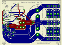
wow, impressive 3D design! May I ask you for eagle3d model of lm3886?
Thanks, quint
Further to Tobias response, here' the lines of code I changed.
#macro USER_TO220(value,H_V,number_of_pins)
#local G = 1.77;
#local G = 1.77;
union { object { TO220Body (value) rotate -90*x translate <0,3.5,6> } object { TO220PinV( (((number_of_pins-1)/2)+1),((number_of_pins-1)/2) ) } }
#macro TO220_11V(value)
object{USER_TO220(value,1,11)}
#end
I was going to make it work for LM1875 but never got around to finishing it.
Tobias,
Your spades look better than mine, but I think the spades need to sit flush with the PCB. As you can see I haven't put the taper on the spade yet. If you can send me the code for that taper I'd really appreciate it. 😀 Rotating intersecting solids in 3D hurts my brain a little.
Attachments

Hello Greg!
Here ya go
#macro KABELSKO()
difference{
union{
box{<-3.15,0,-0.4><3.15,11,0.4> texture{col_silver}}
box{<-3.15,-3.5,-0.4><-1.75,0,0.4> texture{col_silver}}
box{<1.75,-3.5,-0.4><3.15,0,0.4> texture{col_silver}}
box{<-3.8,1.25,-0.4><3.8,3.25,0.4> texture{col_silver}}
}
cylinder{<0,7,-1><0,7,1>1 texture{col_silver}}
box{<4,9,-1><7,11,1> texture{col_silver} rotate z*45}
box{<-7,9,-1><-4,11,1> texture{col_silver} rotate z*-45}
box{<-4,2.22,-5><4,7,-12> texture{col_silver} rotate x*79}
box{<-4,2.22,12><4,7,5> texture{col_silver} rotate x*-79}
}
#end
It is supposed to be nr.5 here:
http://www.elfa.se/images/highres/h3892.jpg
Cheers
Hi tobias,
Thanks for the code for your spade. I was able to complete mine. 😉
Here's a new picture. These are a slightly different design to the ones you are using, that's why they are flush with the PCB.
Maybe we should have a thread for Eagle components and Eagle 3D models.
Thanks
Thanks for the code for your spade. I was able to complete mine. 😉
Here's a new picture. These are a slightly different design to the ones you are using, that's why they are flush with the PCB.
Maybe we should have a thread for Eagle components and Eagle 3D models.
Thanks
Attachments

Maybe we should have a thread for Eagle components and Eagle 3D models.
And maybe a small tutorial for nitwits like me who can't seem to manage to create a board with it
 . To be honest, I don't spent that much time with it to fully master it. To busy with work.
Regards
Yeah, we should have like our own big library 🙂
It's to bad I haven't found any converter from Inventor or Pro/E, then we would be talking! 🙂
It's to bad I haven't found any converter from Inventor or Pro/E, then we would be talking! 🙂
Ok folkes, don't let me down. I have received a ton of email about a GB for this PCB. I have started a thread to organize a group buy.
here:
http://www.diyaudio.com/forums/showthread.php?s=&threadid=62359
Cheers!
Russ
here:
http://www.diyaudio.com/forums/showthread.php?s=&threadid=62359
Cheers!
Russ
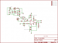
Will Brian do a parts kit for Mr. Ed ? With the lower part count vs Rev C how much do you think the parts kit would cost for this design ?
Also I was thinking about making holes and connectors on that board so that I could screw on an addon-pcb ontop of it, that card would be a buffer and substitute the inputcap.
The circuit was found on Decibel Dungeon (Andrew Rothwell's design I believe)
http://www.ettnet.se/~tobias/diy/mr_ed/gcbuff_bott.jpg
http://www.ettnet.se/~tobias/diy/mr_ed/gcbuff_top.jpg
The circuit was found on Decibel Dungeon (Andrew Rothwell's design I believe)
http://www.ettnet.se/~tobias/diy/mr_ed/gcbuff_bott.jpg
http://www.ettnet.se/~tobias/diy/mr_ed/gcbuff_top.jpg
squalor said:Will Brian do a parts kit for Mr. Ed ? With the lower part count vs Rev C how much do you think the parts kit would cost for this design ?
Yes, that is the plan. 🙂
Certainly, a Mr. Ed kit will be cheaper than a MyRef Rev C monobloc. 🙂 I don't think anyone would be disapointed with the sound. 🙂
The addition of the bypass film cap in the NFB loop is a nice improvement.

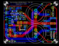
Re: Re: schematic
Great work Tobias,
I really like your design a lot. I personally just don't like vias very much, so I tried to avoid them in my PCB. Otherwise our are quite similar. 🙂 Well obviously 😀.
I really like you buffer idea, the NI chiamp rarely needs one (unless I suppose you are using a tube preamp, or soming else with high output impedance). Because the input impedance is high(100K in my circuit) almsost any low output impedance source is acceptable . But, a good buffer can't hurt! 😀
I do have another design which that solution would be perfect for! It a new version of my "inverting-not" circuit, but thats for another thread. 😀
Cheers!
Russ
tobias_svensk said:Nice Russ
Here's my version that I'm hoping to build some day, it's with separate diodes (MUR860).
tobias_svensk said:Also I was thinking about making holes and connectors on that board so that I could screw on an addon-pcb ontop of it, that card would be a buffer and substitute the inputcap.
The circuit was found on Decibel Dungeon (Andrew Rothwell's design I believe)
http://www.ettnet.se/~tobias/diy/mr_ed/gcbuff_bott.jpg
http://www.ettnet.se/~tobias/diy/mr_ed/gcbuff_top.jpg
Great work Tobias,
I really like your design a lot. I personally just don't like vias very much, so I tried to avoid them in my PCB. Otherwise our are quite similar. 🙂 Well obviously 😀.
I really like you buffer idea, the NI chiamp rarely needs one (unless I suppose you are using a tube preamp, or soming else with high output impedance). Because the input impedance is high(100K in my circuit) almsost any low output impedance source is acceptable . But, a good buffer can't hurt! 😀
I do have another design which that solution would be perfect for! It a new version of my "inverting-not" circuit, but thats for another thread. 😀
Cheers!
Russ
Hehe, I wonder just how many ideas you have going on over there? 😀
And yeah the vias.. I must have been drunk or something
Cheers m8
And yeah the vias.. I must have been drunk or something
Cheers m8
Re: Re: Re: schematic
Hehe, yeah I'm not gonna say anything else than that it from the beginning was a total ripoff layout wise from your first design 🙂
😀
Russ White said:
Otherwise our are quite similar. 🙂 Well obviously 😀.
Hehe, yeah I'm not gonna say anything else than that it from the beginning was a total ripoff layout wise from your first design 🙂
😀
- Status
- Not open for further replies.
- Home
- Amplifiers
- Chip Amps
- My NI chipamp Mark-II - Mr. Ed :)