Hello guys,
I need your help, my actual plan is to build an old amplifier that he was very appreciate in the 95's !
You can find the article here :
https://amplifredy.wordpress.com/2009/02/08/amplificateur-hexo-iii-the-hexorciste-is-rising-again/
There is a link for download the complete file.
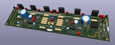
I have made my own PCB, because he must enter in my case (the original PCB is too big).
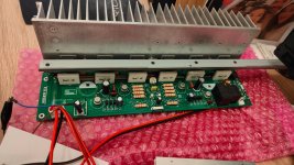
The PCB was produced and assembled recently, and I started the first tests this week.. Unfortunately, the amp oscillate strongly, to around 250Khz.
I respected all values indicated in the project, the only difference are the output transistor, that I replaced from IRF630 to IRFP240 and IRF9630 to IRP9240.
I tried to add a 120p to the input (C26), and a Zobel filter, but same way (and the filter don't like the oscillating honestly xD)
The author indicate that it is prohibited to put a scope to the S and G of the Hex, because the amplifier enter in oscillating in this case. OK, but how can I check this problem ?
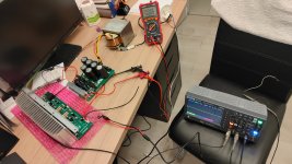
Below my PCB. All grounds are respected, of course.
Bias works, he can be modified. 0.2A minimum without load (it should be around 90mA with the actual PSU, with 2x63V... Difference should be due to the oscillating)
Help please 🙂
I need your help, my actual plan is to build an old amplifier that he was very appreciate in the 95's !
You can find the article here :
https://amplifredy.wordpress.com/2009/02/08/amplificateur-hexo-iii-the-hexorciste-is-rising-again/
There is a link for download the complete file.
I have made my own PCB, because he must enter in my case (the original PCB is too big).
The PCB was produced and assembled recently, and I started the first tests this week.. Unfortunately, the amp oscillate strongly, to around 250Khz.
I respected all values indicated in the project, the only difference are the output transistor, that I replaced from IRF630 to IRFP240 and IRF9630 to IRP9240.
I tried to add a 120p to the input (C26), and a Zobel filter, but same way (and the filter don't like the oscillating honestly xD)
The author indicate that it is prohibited to put a scope to the S and G of the Hex, because the amplifier enter in oscillating in this case. OK, but how can I check this problem ?
Below my PCB. All grounds are respected, of course.
Bias works, he can be modified. 0.2A minimum without load (it should be around 90mA with the actual PSU, with 2x63V... Difference should be due to the oscillating)
Help please 🙂
Attachments


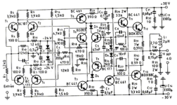
What I see is a blurry picture of a schematic with reference designators but without any component values. A poor starting point for help this is.
You can DL the complete article on my link above (microsoft account required), below is my project under Kicad
Edit : I added the PDF on my drive :
https://drive.google.com/file/d/12nEOzL1qvuoyMvatywV4ctH_ziG9FEQw/view?usp=sharing
Edit2:
I have not made the PSU indictaed in the article, my PSU is a standard "Bridge/Capacitor" (with 2x30000u).
Edit : I added the PDF on my drive :
https://drive.google.com/file/d/12nEOzL1qvuoyMvatywV4ctH_ziG9FEQw/view?usp=sharing
Edit2:
I have not made the PSU indictaed in the article, my PSU is a standard "Bridge/Capacitor" (with 2x30000u).
Attachments

Try 100pF between base and collector of each of Q5 and Q7. However there might be a better approach to compensation with a symmetric dual VAS circuit like this.
You have no local power supply bypass capacitance. I'd add at least 1000 uF on each rail where the power enters the board.
+1 for Miller capacitance on the VAS.
Tom
+1 for Miller capacitance on the VAS.
Tom
Ok I will try to add around 100p on the VAS transitors.
100uF is recommended by the author, there is 2x30000u just before ...
C7/C11 are 100n/250V.
Nothing bad with the output transistor installed (I think no, but I ask !) ?
Edit :
I tried the amp with a lab PSU, 2x32V max, no more. The oscillating was present, so the PSU is not the cause, I think.
100uF is recommended by the author, there is 2x30000u just before ...
C7/C11 are 100n/250V.
Nothing bad with the output transistor installed (I think no, but I ask !) ?
Edit :
I tried the amp with a lab PSU, 2x32V max, no more. The oscillating was present, so the PSU is not the cause, I think.
As pointed above put 47-68pF caps from bases to collectors of Q5/Q7 and also remove R24/R25
wich are limiting the OLG, there are other necessary changes but for the time test these ones.
Thoses amps are known to be half baked, the designer used as basis for all his designs the schematic
below, published by SGS and wich was previously published in this Radio Plans review back in 1977-78 :
wich are limiting the OLG, there are other necessary changes but for the time test these ones.
Thoses amps are known to be half baked, the designer used as basis for all his designs the schematic
below, published by SGS and wich was previously published in this Radio Plans review back in 1977-78 :
Attachments
I would check/try the following steps - make sure to power up the amplifier with a current limiter - I use the traditional 60W bulb on AC input.
1. Check with the scope if the +V and -V are clear (no oscillation). If the oscillation is there, the you need decoupling.
2. Check the mosfet Drain (pin2) are not oscillating - if yes, you need to decouple there.
3. Check with the scope if between ground points you find zero voltage (DC/AC) - scale of milivolts just to make sure ground is unique
4. Try to limit the bandwidth on the feedback resistor - As I could see, I think it's R37 - so attach a paralel capacitor to it (from 1nF to 10nF) - try different values and observe the result and frequency response if the oscillation stops.
5. You can add small capacitors between output mosfet Gate (pin1) and Source(pin3) - try around 1nF - You can try first on N and after on P or on both just to see if oscillation stops. If it stops, you need to check overall performance.
If oscillation stops in any step, try to reduce capacitance as much as possible as long as the oscillation doesn't come back.
So, use small capacitors as possible.
Ah. I didn't see C7, C8, C11, C12 as decoupling caps as I missed the ground symbol in the middle of the schematic. 100 uF should be enough for stability without significant load current. It may not be enough for stability at full output.What about C7, C8, C11, C12, C17, C18?
100uF per rail is plenty for stability I think.
C17, C18 are 'behind' resistors so they won't help much with overall stability. I wouldn't be surprised if the 100 uF vs 1000 uF could set the scene for motorboating either.
The input and output capacitance of the IRFP240 is quite a bit higher that that of the IRF640. Nearly 2x higher for the output capacitance. Could that be a factor? Mouser has plenty of the IRF630/9630 in stock at about a dollar each so it wouldn't be very expensive to try them.
Tom
C17/C18 might act to prevent output stage to input stage feedback through the rails, so could be said to stabilize the amp too.
I have not soldered C17/C18 because I made a mistake on the caps size :/ I have no caps 80V/100V in the good size in my hand for now
@tomchr : I have some IRF630 in my stock, I will test with them, if all others tests are nok.
I re-checked my schematic and I see that I used10n instead of 47n for C15, surely not the cause of the issue, but ...
@tomchr : I have some IRF630 in my stock, I will test with them, if all others tests are nok.
I re-checked my schematic and I see that I used10n instead of 47n for C15, surely not the cause of the issue, but ...
Update !
Good news, issue is solved ! I added 2 caps (50p) to Q5/Q7, and replace the bad value of C15 from 10n to 47n
I got a good sine wave, and idle current when the bias is set to the minimum is 90mA, as mentioned in the original article 🙂
Now, I will check if the issue is solved by the new value of C15, or by the 2 caps added. Update soon !
Attachments
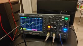
OK the oscillation is solved by the two small caps on Q5/Q7.
I measure 44v pk-pk (6ohms) just before the smooth clipping enter in action.
I checked some temp and I see that Q8/Q9 are very very hot after 30s, I can't keep my finger on it :/ I added two heatsink, but same way... Too hot !
The temp is not depending of the output power (transistors are hot even if the output power is low).
Unfortunately the TO39 are difficult to cool down :/ I will try to handmade a heatsink !
Last edited:
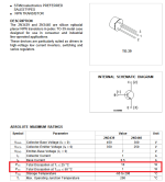
The mosfet driver stage works in class-A and from my calculations we have 60V / 2200 = 27mA quiescent current.
Is your power supply +/-60V?
Is the circuit as in the schematics? So 4 x 2.2kohms resistor (series/paralel)?
If yes, we have 60*0.027 = 1.6W which is more than 1W, which is the maximum power dissipation for this transistor according to the datasheet (2N5416).
Is your power supply +/-60V?
Is the circuit as in the schematics? So 4 x 2.2kohms resistor (series/paralel)?
If yes, we have 60*0.027 = 1.6W which is more than 1W, which is the maximum power dissipation for this transistor according to the datasheet (2N5416).
+/- 63V without load yes
I mounted this heatsink :
https://fr.aliexpress.com/item/1005...t_main.86.21ef5e5bBG9AXl&gatewayAdapt=glo2fra
But it seems not enough (and there is no datasheet on this part). I will try to found a bigger heatsink.
-> Is the circuit as in the schematics? So 4 x 2.2kohms resistor (series/paralel)?
Yes it is 2x2.2k in series, and 2x2.2k in paralal = 2.2k
Hi! Without heatsink, considering Ta (ambient temperature) maximum power is just 1W.
So you cannot operate this circuit without heatsink on Q8/Q9.
Maximum power is 10W as long as the Tc (case temperature) is kept at 25C.
So you really need to bring the temperature down in order to operate it safely
Rth(j-c) = 17.5 C/W (junction to case resistance in celsius/watt)
If you consider 1.8W, Tc will be 1.8*17.5=31.5C above the Tj.
Considering max Tj (junction) = 150C, you need to keep Tc (case temperature) below 150-31.5 = 118C at maximum.
Heatsink minimum resistance = 118-50(ambient)/1.8 = 37.7C/W
I would operate with some margin of at least around 30C, so I would bring the case temperature down to a maximum of 90C.
In this case you would need a heatsink with minimum resistance of 16C/W.
The one from Aliexpress that you indicated probably is not enough.
Maybe a hand made will do the job - Just meaure the temperature and adjust it.
For this stage with Q8/Q9 a TO-126 or TO-220 encapsulation would be more appropriate since they allow bigger heatsinks with screw.
Regards!
Attachments

- Home
- Amplifiers
- Solid State
- My new amp oscillate :/