Try, if I may suggest, the 1dB steps. Enough is enough, practice shows. 🙂I have not really need 0.25dB step for the moment. 0.5dB is enough for me ..........but if one day, I have the MUSES72323 chip, i will update...
That's why I like your project!You are right 🙂 , That's is the reason that in the software project , when you turn quickly the encoder... the step change to 1dB or 2db (during rotation moment ).
Because from -80Db to 0dB if it stay with 0.5dB per step ; it will take long long time ..... 🙂
I just replaced it now with a bigger display (1.5" to 2.4")
I'm waiting patiently for you to have a Muses72323 and make a program with MUTE function. 😉
Hello! Thanks for the work done, this is exactly the solution I was missing for my pass 1.7.
I noticed a bug with switching inputs with the encoder, when I go to increase 1 -> 2 -> 3 -> 4 everything is fine and when I go to decrease then input 3 is skipped and outputs 4 -> 2 -> 1
And in the future I would like to see the inclusion from the remote control ))
PS: If you want to play with Muses72323, I have an extra one and I can send it to you for free.
I would also like to use this regulator for a balanced connection, as far as I understand I need to make another muses board and connect it in parallel to the controller and then I can connect it according to this scheme
R channel balanced input connect + to R/- to L one muses board, output R to +/L to - to R inputbalanced amp
L channel balanced input connect + to R/- to L two muses board, output R to +/L to - to L inputbalanced amp
Do I understand everything correctly? Thank you!
R channel balanced input connect + to R/- to L one muses board, output R to +/L to - to R inputbalanced amp
L channel balanced input connect + to R/- to L two muses board, output R to +/L to - to L inputbalanced amp
Do I understand everything correctly? Thank you!
Yes , You can put them in parallel.
But I think that for the aleph P1.7 , it is better to put the volume controller in the output and the MUSES is not made for that.
Are you sure to put it in the input ?
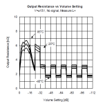
Note that the MUSE need an high inpendance input for the preamp.
The output impedance of the MUSES is high.
The note in the datasheet

Rbias is the input impedance of the follower.
But you can try, there are no risk if the muses is in the input

i have built an apleh P and I use an KHOZMO shunt attenuator in the output.
I'm planning to built an digital relay based output attenuator for my alehp when I have alittle time.
I will correct the bug soon, Thank you for the report
But I think that for the aleph P1.7 , it is better to put the volume controller in the output and the MUSES is not made for that.
Are you sure to put it in the input ?
Note that the MUSE need an high inpendance input for the preamp.
The output impedance of the MUSES is high.
The note in the datasheet

Rbias is the input impedance of the follower.
But you can try, there are no risk if the muses is in the input

i have built an apleh P and I use an KHOZMO shunt attenuator in the output.
I'm planning to built an digital relay based output attenuator for my alehp when I have alittle time.
I will correct the bug soon, Thank you for the report
Attachments
Lalaina,
This is an excellent project, simple implementation of the MUSES72320. I'm considering building one based on your code. I'm really a hardware person but terrible at coding, so need to rely on code from others.
A few questions:
1. I've never used the MUSES chip before and how does it deal with on/off cycles, does it remember it's last settings? I've read in the datasheet that you need to put it to mute first before removing power
2. How does you code implement an on/off sequence? or you just remove power via a hardware switch?
2. The OLED display you have used appears to be a 128 x 64 OLED display with a SH1106 or SSD1306 controller, is that correct?
Thanks
Patrick
@altus fidelitas
1. I've never used the MUSES chip before and how does it deal with on/off cycles, does it remember it's last settings? I've read in the datasheet that you need to put it to mute first before removing power
-> As you have seen in the datasheet, the MUSES chip don't have any eeprom to store any parameter or setting. In my project, this function is handled by the microcontroller ( it has an EEPROM). the microcontroller record all setting ( volume level, input setting, OLED brithnes ......) , and restore in boot sequence ( off to on)
2. How does you code implement an on/off sequence? or you just remove power via a hardware switch?
-> No . if you read the shematic, there are any on/off bouton . ( only menu, up, down)
2. The OLED display you have used appears to be a 128 x 64 OLED display with a SH1106 or SSD1306 controller, is that correct?
-> As I mentioned in the first post, it use SSD1309 in SPI mode .
gretting from MADAGASCAR 🙂
Working on the new MUSES 72323 new volume kit.
I really like these new IPS LCD (not the TN old one with bad angle vision), their contrast is very good. I like when the back groubd is really black ( that' why I used OLED before)
I'm new in the STM32 world, it took me long time to learn the CUBE IDE STM32 dev tools.
still long to do list........
I really like to put color every where 😉
Hi lalaina!Working
It's great project!
Is the MUTE function built in? 😉
Well done. This screen already looks very good.Working on the new MUSES 72323 new volume kit.
I really like these new IPS LCD (not the TN old one with bad angle vision), their contrast is very good. I like when the back groubd is really black ( that' why I used OLED before)
We are also waiting for a light, laconic version, just some numbers from 0-100%
- Home
- Source & Line
- Analog Line Level
- My MUSES 72320 volume control
