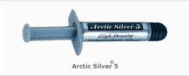
You mean should I solder back plate of transistor with a copper plate and then mount it on heat sink. It seem practically difficult to achieve. and might damage active device due to solder heat.,Almost but with a live connection (maybe even soldered) between the transistor and the plate, and multiple plates if the transistors cant be connected together. Kind of like:
(Transistor)
---Solder---
------------Plate------------------
----------Insulator---------------
---------------------heat sink------------------------
Can Arctic Silver Heat Sink compound be used?. Mr Elvee the moot question is whether there will be any advantage in thermal conduction by placing any intermediate sheet be it copper or Aluminium between transistor and heat sink.You may replace the soldering with silver thermal paste: the difference in performance will be minuscule
Your advice on the subject will be beneficial to the Forum Boarders.
Attachments
You can use arctic silver, and it becomes advantageous if the heat-spreader has a very low thermal resistance (thus preferably copper or very thick aluminum), and has an area significantly larger than the transistor's tab
https://www.diyaudio.com/community/threads/unusual-amp-from-1987.357369/post-6414466
In this post, you can see aluminum slab, with copper spreaders ready to be machined.
The disadvantage is that you need bigger thermal pad (or whatever it is, mica, etc...) between heat-spreader and the actual heatsink.
In this post, you can see aluminum slab, with copper spreaders ready to be machined.
The disadvantage is that you need bigger thermal pad (or whatever it is, mica, etc...) between heat-spreader and the actual heatsink.
Mr Elvee,
I searched data of so many MOSFET to make a high power MOSFET version of Circlophone using single device but could not find suitable MOSFET for the same. Some IXYS MOSFET have higher power and current rating but their SOA was not that good and are very expensive. I therefore decided to make higher power version by paralleling two IRFP240 MOSFET together.
I have added another set of current sensing resistors with the exixting one to keep quescient current of each MOSFET same. I have added 0.2 ohm resistor in each of the MOSFET Drain to limit the current and for better sharing of current. I have also added 10 ohm gate stopper resistor in each MOSFET Gate. I have procured higher current rating power schottky MBR1645.
The simulation results seem good. I am attaching the out put wave form and FFT waveform for 1khz and 50khz. The THD is around 0.003%.
I need your technical advice for this modification whether this is suitable from the point of view of stability. If you approve it then I will modify my exixting


 prototype board for the same.
Thanks
I searched data of so many MOSFET to make a high power MOSFET version of Circlophone using single device but could not find suitable MOSFET for the same. Some IXYS MOSFET have higher power and current rating but their SOA was not that good and are very expensive. I therefore decided to make higher power version by paralleling two IRFP240 MOSFET together.
I have added another set of current sensing resistors with the exixting one to keep quescient current of each MOSFET same. I have added 0.2 ohm resistor in each of the MOSFET Drain to limit the current and for better sharing of current. I have also added 10 ohm gate stopper resistor in each MOSFET Gate. I have procured higher current rating power schottky MBR1645.
The simulation results seem good. I am attaching the out put wave form and FFT waveform for 1khz and 50khz. The THD is around 0.003%.
I need your technical advice for this modification whether this is suitable from the point of view of stability. If you approve it then I will modify my exixting
Thanks
With MOSfets like the IRFP240, the matching is much more important than any balancing resistors: they just act like icing on the cake when the matching is done properly.
They are useful for avoiding differential thermal runaway, but if the FETs are mismatched they will do nothing useful
They are useful for avoiding differential thermal runaway, but if the FETs are mismatched they will do nothing useful
The resistors, if you use them, should be placed in series with the source: that's where the effect will be maximal
Have been collecting parts for trying out the Circlophone.
Can I replace the 470uF dc blocking cap C3 by a larger value one(2700uF/16V) I happen to have at hand?
thanks and regards.
Can I replace the 470uF dc blocking cap C3 by a larger value one(2700uF/16V) I happen to have at hand?
thanks and regards.
Why not? no benefit, but the only risk is a slightly longer settling time in case the input pair is poorly matched
Probably not worth the trouble: you just risk a few tens of mV offset at the output for a few seconds. Totally unnoticeable, for you, and more importantly for the speaker
Mr Elvee,
What is the role of combination R1 & C2 connected across the diodes 1n4148. Is this the requirement of PSRR (Power supply-rail rejection)?
Thanks
What is the role of combination R1 & C2 connected across the diodes 1n4148. Is this the requirement of PSRR (Power supply-rail rejection)?
Thanks
They are part of the loop filter of the vertical current loop servo (determining the quiescent current, etc.). The horizontal loop is just the regular negative feedback, just like in most amplifiers
Would 2SC3856 be a useable transistor. for +/- 25 to +/- 28 volts supply, 8ohm speaker. I just trying to expand the useable transistors...
- Home
- Amplifiers
- Solid State
- ♫♪ My little cheap Circlophone© ♫♪
