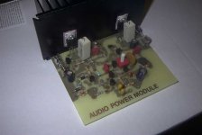
I thought I'd share my latest almost finnished amp with all.
It's basicly a p3a front-end with constant current instead of the boot strap and then into a tip122 quasi output but at a lower voltage so I could use 2n390X throught out.
It was made with parts on hand so some values are less then optimum like the 33p cap in the front-end should of been larger.
It's basicly a p3a front-end with constant current instead of the boot strap and then into a tip122 quasi output but at a lower voltage so I could use 2n390X throught out.
It was made with parts on hand so some values are less then optimum like the 33p cap in the front-end should of been larger.
Attachments

it looks good.
one observation: since you alread have the ccs there, why don't you just add one transistor so that the input stage also has a ccs?
one observation: since you alread have the ccs there, why don't you just add one transistor so that the input stage also has a ccs?
Good point, I don't know.
I have the student version of pspice so 10 bjt or less but I could of done the front end seperate from the rest to work out genral values and soft analisys.
I think I'll revise.
Thanks
I have the student version of pspice so 10 bjt or less but I could of done the front end seperate from the rest to work out genral values and soft analisys.
I think I'll revise.
Thanks
by the way, what does R18 (220ohm) do for you?
I only had a 500 ohm pot on hand and this would not work. So I added the 220 ohm r to get me into the 500~700 ohm range which would get me a fair amount of offset control and get the A class vas to work properly.
but isn't it shorted by the wiper? maybe you wanted to put it above the trimmer, depending on the desired value of the resistor / trimmer combination.
r18 is on the otherside of the trimmer, it's just a typo I made recreating the circuit in eagle to post online.
Revision
Here's the reivsed.
I like to to keep simple things simple, but Millwood if your reading, do you think by using a shared ccs in the df stage I will be introducing more noise by the flucutuations caused by the vas, than I can wrinkle out by the increased gain of the new df's ccs vs negative feedback?
I have one made already, I'll make another with the revisions and see which looks good.
Attachments
What about the g19er? Does that affect the other g19er? I just made a 10,000 watt amp and it really rocks. If you want the schematics no problem.
It has 50 transisters in a row! It gets very hot so I have a house fan cooling it.
It has 50 transisters in a row! It gets very hot so I have a house fan cooling it.
How 'bout the possibility of using the TIP127 as the complement to the TIP122? Then the circuit should have more stability and you can omit Q8 and Q9.🙂 One idea to facilitate serious circuit design while avoiding a lot of need to deal with lower level interaction with circuit programs is to try mc7demo.
subwo1 said:How 'bout the possibility of using the TIP127 as the complement to the TIP122? Then the circuit should have more stability and you can omit Q8 and Q9.🙂 One idea to facilitate serious circuit design while avoiding a lot of need to deal with lower level interaction with circuit programs is to try mc7demo.
hEY dO U KNOW THAT qUASI cOMPLEMENTARY IS THE sTAGE WHICH IS PREFERRED MOSTLY IN pROFESSIONAL aUDIO BECAUSE OF ITS sYMMETRIC CURRENT CONSUMPTION OF BOTH RAILS AND THE CURRENT DRIVE IS MORE ROBUST AND THE SOUND QUALITY HAS SOME MORE EXERTING PRESSURE IN TERMS OF COMPLEMENTARY DESIGNS.
rEGARDS
aMpMAn
- Status
- Not open for further replies.
- Home
- Amplifiers
- Solid State
- my latest amplifer