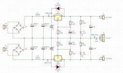
After looking around the forums and copying a few good ideas I'm taking my first shot at PS design so be nice! My goal here is to build a very basic +/-12 supply capable of delivering 100ma or more and fit on a smallish PCB. I realize the sky is the limit in regulator design but I'm trying to master the basics here and build on that later. The only suggestions I'm pondering right now, but I'm open to others, is whether I need to keep C5 and C6 and where to find some 'high ESR' electrolytics for C9 and C10?
Regards,
Dan

Regards,
Dan
Attachments
Why not use green LEDs as a complement/instead of, to R1 and R2?
>20dB in less noise.
2 leds is giving 5Vout, and combined with a resistor and/or more LEDs you can tune output.
More tips and tricks is found here:
Using 3-pin regulators off-piste: part 1
>20dB in less noise.
2 leds is giving 5Vout, and combined with a resistor and/or more LEDs you can tune output.
More tips and tricks is found here:
Using 3-pin regulators off-piste: part 1
Why not use green LEDs as a complement/instead of, to R1 and R2?
>20dB in less noise.
2 leds is giving 5Vout, and combined with a resistor and/or more LEDs you can tune output.
More tips and tricks is found here:
Using 3-pin regulators off-piste: part 1
Very interesting...........🙂
I'm going to deem my final schematic as a good basic 'datasheet' regulator. I've followed the basic guidelines of the datasheet plus a couple of twists. This will get me started and I can't wait to put my scope on it and perhaps then pursue some 'upgrades'.
Regards,
Dan

Regards,
Dan
Attachments

Looks alright. With a decent layout, these should serve you well.
Why this much LED current though? Those are going to be fairly bright, possibly more so than you want for what I assume are "yep, this voltage works" indicators. You might have needed 20 mA 40 years ago, but things have gotten a hair more efficient since then.
Why this much LED current though? Those are going to be fairly bright, possibly more so than you want for what I assume are "yep, this voltage works" indicators. You might have needed 20 mA 40 years ago, but things have gotten a hair more efficient since then.
With only a scope TS have no chance to make real low-noise thing. It can't be seen. You need something more.
C5 & C6 not needed if reg within a few cm of the 1000uF.
C9 & C10, you can add series R to compensate for low ESR.
If you have separate transformer secondaries you can make two identical LM317 regs and wire them in series.
C9 & C10, you can add series R to compensate for low ESR.
If you have separate transformer secondaries you can make two identical LM317 regs and wire them in series.
C5 & C6 not needed if reg within a few cm of the 1000uF.
C9 & C10, you can add series R to compensate for low ESR.
If you have separate transformer secondaries you can make two identical LM317 regs and wire them in series.
It was a great 'starter' project for me. In the future it will be the foundation for some of the great ideas available in this forum.
Regards,
Dan
One other thing. You need a resistor in series with each inductor to damp out the resonance with the smoothing cap. 1 ohm would do: the sum of the inductor’s series resistance and an external resistor.
C5 & C6 not needed if reg within a few cm of the 1000uF.
C9 & C10, you can add series R to compensate for low ESR.
If you have separate transformer secondaries you can make two identical LM317 regs and wire them in series.
Yupp --the ESR of the filter capacitor is important -- a low ESR value is NOT recommended with the LM317 as it may cause instability. Over 100 milliOhms please.
- Home
- Amplifiers
- Power Supplies
- My KISS LM317/LM337 Regulator