> Could you post a simplified working circuit of your Distortion Magnifier ?
I'll certainly second that .....
🙂
Patrick
I'll certainly second that .....
🙂
Patrick
EUVL,
good idea to build it with SMD components.
Maybe you could use analog switches, type 4066 or similar, to switch resistance and capacitance. (As you've surely realized I would not use the rotary switch. I would be able to replace them with the analog switch but do not know if this would lead to a degradation in performance).
Certainly at this point would be even nicer to use the best performing components.
Add, as suggested by Bob, a frequency counter, a RMS digital voltmeter, etc. ..
Although it would retain the "core" !
But these things are outside my ability.
Maybe you ....?
Regards
Giuliano
> a frequency counter, a RMS digital voltmeter, etc. ..
You can buy them for less money than DIY.
But that is also true for the analyser.
Also there are enough DIY projects on the inet for those. Pls google.
Patrick
You can buy them for less money than DIY.
But that is also true for the analyser.
Also there are enough DIY projects on the inet for those. Pls google.
Patrick
Of course, Patrick. Not a problem for me to build frequency counter or RMS to DC converters, there are many schemes in the network.
Replace the 1496 and / or implement a new AGC with gain control voltage IC, in this I mean.
Maybe in future...I will become good...meanwhile I build the original which is already a good thing!
Thanks and Regards
Giuliano
Replace the 1496 and / or implement a new AGC with gain control voltage IC, in this I mean.
Maybe in future...I will become good...meanwhile I build the original which is already a good thing!
Thanks and Regards
Giuliano
EUVL,
good idea to build it with SMD components.
Maybe you could use analog switches, type 4066 or similar, to switch resistance and capacitance. (As you've surely realized I would not use the rotary switch. I would be able to replace them with the analog switch but do not know if this would lead to a degradation in performance).
Certainly at this point would be even nicer to use the best performing components.
Add, as suggested by Bob, a frequency counter, a RMS digital voltmeter, etc. ..
Although it would retain the "core" !
But these things are outside my ability.
Maybe you ....?
Regards
Giuliano
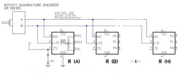
IC analog switches are a definite possibility, but I don't know how much degradation would be introduced. I would definitely replace the range switch with a relay arrangement. The frequency tuning switch might be able to be replaced with a four-gang, well tracking potentiometer arrangement. Depending on noise and distortion degradation, replacement of the frequency tuning switch by some kind of IC VCA's might be an option as well. Use of a PIC microcontroller is also a definite possibility.
Cheers,
Bob
This is a simplified schematic of the use of solid-state gang potentiometer.
Removing the CS, except one, you can perform the calibration potentiometers.
Bob, you write "four-gang potentiometer", but should not be eight resistors of S3 ?
Forgive me if I said something obvious or wrong, but I'm not very expert.
Regards
Giuliano
Removing the CS, except one, you can perform the calibration potentiometers.
Bob, you write "four-gang potentiometer", but should not be eight resistors of S3 ?
Forgive me if I said something obvious or wrong, but I'm not very expert.
Regards
Giuliano
Attachments
Last edited:
sadly there is not much description available...🙁
Regards
Sorry 'bout that! I thought I had posted it.
I'll see if I can dig out the info.
Cheers,
Bob
I started building my Cordell analyzer when the article came out. I didn't have many resources, parts or smarts, so it took me three years to finish it. After all this time some of the front panel lettering has worn off, but I still use it often in spite of having other analyzers available. The noise floor and residual beats 'em all. Here's a couple photo links-
http://www.conradhoffman.com/BC_thd_face.jpg
http://www.conradhoffman.com/BC_thd_internal.jpg
http://www.conradhoffman.com/BC_thd_face.jpg
http://www.conradhoffman.com/BC_thd_internal.jpg

I started building my Cordell analyzer when the article came out. I didn't have many resources, parts or smarts, so it took me three years to finish it. After all this time some of the front panel lettering has worn off, but I still use it often in spite of having other analyzers available. The noise floor and residual beats 'em all. Here's a couple photo links-
http://www.conradhoffman.com/BC_thd_face.jpg
http://www.conradhoffman.com/BC_thd_internal.jpg
Very good, really well built it!
Giuliano
Distortion Magnifier
Here is a brief description of the Distortion Magnifier that I dug out, as a Word Document. It includes block diagrams.
Hope this helps.
Cheers,
Bob
Sorry 'bout that! I thought I had posted it.
I'll see if I can dig out the info.
Cheers,
Bob
Here is a brief description of the Distortion Magnifier that I dug out, as a Word Document. It includes block diagrams.
Hope this helps.
Cheers,
Bob
Perhaps you have forgotten your attachment ?? 
Patrick
PS I have a question about your adjustable baffle step filter, sent earlier by PM. Pls kindly take a look. Thanks.
Patrick
PS I have a question about your adjustable baffle step filter, sent earlier by PM. Pls kindly take a look. Thanks.
I started building my Cordell analyzer when the article came out. I didn't have many resources, parts or smarts, so it took me three years to finish it. After all this time some of the front panel lettering has worn off, but I still use it often in spite of having other analyzers available. The noise floor and residual beats 'em all. Here's a couple photo links-
http://www.conradhoffman.com/BC_thd_face.jpg
http://www.conradhoffman.com/BC_thd_internal.jpg
Conrad,
Thanks for your kind words (and your patience in building it!)
Cheers,
Bob
Perhaps you have forgotten your attachment ??
Patrick
PS I have a question about your adjustable baffle step filter, sent earlier by PM. Pls kindly take a look. Thanks.
I guess that failed. Here I'll try again.
I guess that failed. Here I'll try again.
Looks like I goofed again. Went into "manage attachements", uploaded the file, closed the window, submitted the reply. Seems like it should have worked.
Bob
On behalf of Bob.
Patrick
Thanks, Patrick!
I'll try and dig out something on the variable baffle step compensation circuit I used in my Athena active speaker system tomorrow.
Best,
Bob
- Status
- Not open for further replies.
- Home
- Amplifiers
- Solid State
- My implementation of the Cordell Distortion Analyser