I'm going to build a good 5+1 channel ht with 2*LM1876, 1*LM1875, 1*LM3876.
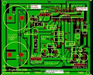
Now there is the PCB of LM1876, Which I designed using PCB Express,
And the schematic is the "Auxiliary Amplifier Circuit" as it was in the official datasheet. I just removed the inductor.
Tell me your suggestions.
And this is the power split supply pcb is here -
Now there is the PCB of LM1876, Which I designed using PCB Express,
An externally hosted image should be here but it was not working when we last tested it.
And the schematic is the "Auxiliary Amplifier Circuit" as it was in the official datasheet. I just removed the inductor.
Tell me your suggestions.
And this is the power split supply pcb is here -
An externally hosted image should be here but it was not working when we last tested it.
Hi,
I don't understand why you think you need different chipamp types for each channel.
Could you explain your reasoning?
I don't understand why you think you need different chipamp types for each channel.
Could you explain your reasoning?
NO...no...
I'm using a LM1876 IC for Front channels, another LM1876 for rear, a LM1875 for center and a LM3876 for Subwoofer.
understand?
I'm using a LM1876 IC for Front channels, another LM1876 for rear, a LM1875 for center and a LM3876 for Subwoofer.
understand?
Why choose three different chipamp types for the different channels?
ok, this may be a solution, to use two LM1876 for front and rear. and one bridged LM1876 for subwoofer. And one LM1875 for centre.
Yeh, this is the best solution.
Now look at my PCB layout.
power supply board.
check polarity on c3,c4 and c7,c8 (+ is on ground lead)
Take away diods on pcb and buy a standalone diod bridge,that u can screw on the heatsink.
nevermind:😕 iam tired,and shouldnt surf,check boards
check polarity on c3,c4 and c7,c8 (+ is on ground lead)
Take away diods on pcb and buy a standalone diod bridge,that u can screw on the heatsink.
nevermind:😕 iam tired,and shouldnt surf,check boards
check polarity on c3,c4 and c7,c8 (+ is on ground lead)
thanks, but, In negative supply rails, the capacitor's positive pole should be connected to the GND, and the negative pole must be connected to the negative.
if you route pin 15 under the 1K resistor just below it and around the outside of the board, you can then evenly space your input leads if you wanted to use a standard connector there.
Get rid of all the copper pours that are not connected to anything. I would suggest trying to make all traces with 45 degree angles only for manufacturing purposes. Also watch for issues with spacing between traces and pads. Your layout has a number of questionable areas where traces appear to be very close to other traces or pads.
if you route pin 15 under the 1K resistor just below it and around the outside of the board, you can then evenly space your input leads if you wanted to use a standard connector there.
thanks, friend, here it is ---
An externally hosted image should be here but it was not working when we last tested it.
Hi Paswa,
I have had a look at your design and there are a few problems with it.
1. 47K resistor is connected between +ve rail and ground it should be connected to C5.
2. Remove the unconnected copper. It forms a parasitic capacitor between pins and can make the amplifier unstable.
3. The power supply should not encircle the signal input. Rectified signal currents flow in the power supply and this can cause distortion if it is coupled back into the input stage. Try to keep the +ve and -ve supplies as close to gether as possible.
4. The star point should connect between the center point of C1 and C2.
5. Power supply in should connect to C1 and C2 before it goes to the amplifer. Power ground should join between the two capacitors.
6. You may need some wire links to make all the connections but it would be much better to do this rather than compromise the design to use PCB tracks.
7. LM1876 should have 100nF power supply decoupling capacitors close to the power pins or it may go unstable.
8. The LM1876 may need to closer to the edge of the PCB depending on your heat sink.
I have attached a rough drawing with some pointers on it.
Regards,
Andrew
Attachments
Get rid of that junk Express PCB and use Eagle instead. I blew up a couple of amps designed with Express because it had the wrong pin description in the library.
. I blew up a couple of amps designed with Express because it had the wrong pin description in the library.
what? what you're sayins? If it is true then my all works for designing PCB will go in vain. Can you explain it?
Not sure about Express PCB. Use EaglePCB, it is free and once you get used to it, you should be good. The free version has a restriction on the PC board size though.
Again on the component libraries provided and pin descriptions, layouts, it is always better to confirm the component information from other reliable external sources or the real parts themselves than to depend only on the library. During the initial stages, I used to literally measure pin widths and component sizes before choosing the closest fit.
Again on the component libraries provided and pin descriptions, layouts, it is always better to confirm the component information from other reliable external sources or the real parts themselves than to depend only on the library. During the initial stages, I used to literally measure pin widths and component sizes before choosing the closest fit.
Paswa said:
what? what you're sayins? If it is true then my all works for designing PCB will go in vain. Can you explain it?
I can tell you that Eagle is much better. Express is fine, but watch out the libraries.
Hey, check it out, I've modified my PCB with the suggestions of my friend Andrew.
Is there any problem remaining?


Is there any problem remaining?
the layout is ok.i have 3 suggestions:
1,the power terminal is too small,i think 200mil lead is better.add more PG pads.
2,for the sginal track,i think 35mil is ok,for the power track i would like use 60mil.i would set the minimum clearance as 20mil.
3,consider how to mounting the chip on the heatsink,you should left enough room on the board for the heatsink or cut the border track(pin 4,8,10).
FYI,the below is my 3886igc layout:

greetings from beijing,
zang
1,the power terminal is too small,i think 200mil lead is better.add more PG pads.
2,for the sginal track,i think 35mil is ok,for the power track i would like use 60mil.i would set the minimum clearance as 20mil.
3,consider how to mounting the chip on the heatsink,you should left enough room on the board for the heatsink or cut the border track(pin 4,8,10).
FYI,the below is my 3886igc layout:
greetings from beijing,
zang
- Status
- Not open for further replies.
- Home
- Amplifiers
- Chip Amps
- My Home theater with LM1876, LM1875, LM3876 For Dummies