Very interesting thread. Thanks to ygg-it for starting it.
Couple of unrelated questions:
- the size of the input choke appears too low for proper choke input. Was it sized based on listening? Or is the purpose not being a choke input supply, but just some hf filtering before the input cap?
- why hybrid rectification?
Not too long ago i spent a day listening to the effects of the first cap in a choke input supply. Much to my surprise did not like any of the films compared to good electrolytics.
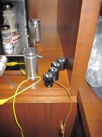
EDIT: Looked at the pics and it appears the tiny choke is something recycled from a smps and it is indeed not a choke input supply
Couple of unrelated questions:
- the size of the input choke appears too low for proper choke input. Was it sized based on listening? Or is the purpose not being a choke input supply, but just some hf filtering before the input cap?
- why hybrid rectification?
Not too long ago i spent a day listening to the effects of the first cap in a choke input supply. Much to my surprise did not like any of the films compared to good electrolytics.
EDIT: Looked at the pics and it appears the tiny choke is something recycled from a smps and it is indeed not a choke input supply
Last edited:
Nice example of a flywheel power supply. I like ASC X386 motor runs - they're very nice quality and not expensive.
I ordered a bunch of them from Allied while in the US for a business trip recently. Otherwise I get them from RS components.
In Italy you should be able to find some motor runs from Ducati, but I have never tried them since they are around $30 each while the ASC's are around $10 each..
I ordered a bunch of them from Allied while in the US for a business trip recently. Otherwise I get them from RS components.
In Italy you should be able to find some motor runs from Ducati, but I have never tried them since they are around $30 each while the ASC's are around $10 each..
- the size of the input choke appears too low for proper choke input. Was it sized based on listening? Or is the purpose not being a choke input supply, but just some hf filtering before the input cap?
- why hybrid rectification?
That is a flywheel power supply. Admittedly, changing the value of the 1st cap can have a significant impact on the B+ and other factors. I would be careful to simulate it before changing its value.
Hybrid rectification (Graetz bridge) works well if your transformer doesn't have a center tap.
Ian
I'm not sure what "visible" intermodulation is, but I am sure that second order distortion will always produce both intermodulation and harmonics.ygg-it said:resulting in increased second harmonic distortion, free from visible intermodulation
Only in a poorly designed SE amp.Decades ago Bartolomeo Aloia, an Italian designer pioneer of the Italian High Fidelity, has proved with incontrovertible instrumental documentation that the signal of an audio amplifier passes even through the power cord towards the electric power transmission line.
True for SE. Maybe a good reason to avoid SE?All the current that circulates in the load, circulates likewise verbatim through the entire power supply unit, as if this were in series to the signal.
Might be more accurate to say "Thus a better AC behaviour of the electrolytic supply capacitors is of minor significance and slightly audible and barely influences overall sonic performance."Thus a better AC behaviour of the electrolytic supply capacitors is significant and greatly audible and influences overall sonic performance.
I am really sorry to have to disappoint you, but there is no "Holy Grail of the amplification", and no crock of gold at the end of the rainbow, and no tooth fairy and no Father Christmas.This solution is actually my Holy Grail of the amplification
Bipolar electroytics may be better than polar electrolytics when used with little or no DC bias. This is because their symmetry means that the lowest order of distortion is 3rd. As soon as you add DC you get 2nd too. If, as is often the case, the DC voltage is higher than the AC voltage then the 2nd will be greater in amplitude than the 3rd would have been without DC. Hence bipolars have their place in passive speaker crossover networks.
Why not? AC ratings are more demanding than DC, so it is fine to use an AC rated cap in a DC application. The converse is not true.I would not use anything electrolytic in DC power supply that in datasheet has "VAC" for the rated voltage parameter.
Very interesting thread. Thanks to ygg-it for starting it.
Couple of unrelated questions:
- the size of the input choke appears too low for proper choke input. Was it sized based on listening? Or is the purpose not being a choke input supply, but just some hf filtering before the input cap?
EDIT: Looked at the pics and it appears the tiny choke is something recycled from a smps and it is indeed not a choke input supply
I have cannibalized the tiny input choke from an ATX power supply and I have replaced the original component in the chinese schematic which was a series 10 ohm resistor: I saved in this way few DC Volts plus got the benefit of adding an RF filter.
Be aware that GZ34 can withstand till 60uF filter capacitor, but 5V4 can withstand 32uF only. So you cannot increase the value of the first capacitor, but you can play with the second one after the bigger main choke.
I appreciates all your inputs (except that there is no tooth fairy and no Father Christmas)...
I read this as, if a capacitor sounds different, then it means that is not linear (i.e. it distorts), so your affirmation makes perfect sense. But we don't know how my NP b-t-b-capacitors distort and, overall, we don't know the overall effect of adding them: better, or not, behavior as standalone caps, they do influence overall sonic performance.
I need to check the construction of Motor Start electrolytic capacitors as, I read, they are not suitable for most DC or continuous AC applications. It is anyway strange that no electrolytic Motor Start cap's datasheet mentions VDC rating, but only shows VAC rating, while for poly films it usually shows both the rating values.
Might be more accurate to say "Thus a better AC behaviour of the electrolytic supply capacitors is of minor significance and slightly audible and barely influences overall sonic performance."
Why not? AC ratings are more demanding than DC, so it is fine to use an AC rated cap in a DC application. The converse is not true.
I read this as, if a capacitor sounds different, then it means that is not linear (i.e. it distorts), so your affirmation makes perfect sense. But we don't know how my NP b-t-b-capacitors distort and, overall, we don't know the overall effect of adding them: better, or not, behavior as standalone caps, they do influence overall sonic performance.
I need to check the construction of Motor Start electrolytic capacitors as, I read, they are not suitable for most DC or continuous AC applications. It is anyway strange that no electrolytic Motor Start cap's datasheet mentions VDC rating, but only shows VAC rating, while for poly films it usually shows both the rating values.
Last edited:
It is possible that some Motor Start capacitors are rated for low duty cycle use only. This is nothing to do with AC or DC, but because of heat build-up due to leakage current. These capacitors are intended for AC use (motor starting!), so the datasheet only gives AC figures. Manufacturers do not fill their datasheets with figures for applications which they did not think of. Most components can be used for a variety of applications, so the absence of a rating does not indicate that the component is unsuitable. For example, high gain valves are often intended for VHF/UHF front-ends and the datasheet shows this, but that does not mean that they cannot be used for audio front-ends.
Decades ago Bartolomeo Aloia, an Italian designer pioneer of the Italian High Fidelity, has proved with incontrovertible instrumental documentation that the signal of an audio amplifier passes even through the power cord towards the electric power transmission line. The study in question highlights how the AC audio signal inevitably passes through the power supply circuit including the transformer and the electrolytic filter capacitors, forming a secondary AC audio path. All the current that circulates in the load, circulates likewise verbatim through the entire power supply unit, as if this were in series to the signal. Thus a better AC behaviour of the electrolytic supply capacitors is significant and greatly audible and influences overall sonic performance.
There seems to be a bit of a muddling of two very different issues here. Yes, in an SET amplifier the final capacitor(s) in the power supply is absolutely in the signal path.
On the other hand, to say that "the signal of an audio amplifier passes even through the power cord towards the electric power transmission line" is a rather misleading statement. Unless the power supply is grossly deficient, there should be essentially no "audio signal" detectable in the current flowing through the power cord. With a class B amplifier, where the power demand rises as the sound level rises, there would certainly be a measurable increase in the power demand from the mains supply during the loud passages, but the capacitors in the amplifier's power supply should be large enough so as not to allow audio-frequency fluctuations in the power demand to make it back to the power transformer and power cord. In a class A amplifier like an SET, the average current draw is essentially constant, and so there would not even be a significant net increase in the power demand during the crescendos in the music. Again, the smoothing capacitors in the power supply should be removing all significant audio-frequency fluctuations in the current draw at the power transformer. It is those final capacitors in the power supply that should be providing the signal path, if the power supply is well designed. Besides, especially in a power supply such as that depicted in the OPs posting, with a very small inductance input choke, the rectifiers will be non-conducting for a significant proportion of the mains cycle, and so during those times there is no way at all that any audio signal could be propagating back to the power transformer and the power cord.
The "bipolar" back-to-back electrolytic capacitors that the OP has introduced seem to serve no legitimate purpose, since in each location the voltage on the top end is always strictly positive with respect to the voltage on the bottom end. In each location, what is really needed is an "ideal" capacitor that acts as near as possible to a dead short at audio frequencies. It is hard to see why introducing a back-to-front capacitor in series would further this goal. If there really is an "audible improvement" when the back-to-front capacitor is installed, then maybe this suggests that some resultant degradation of the smoothing is producing a "sound effect" that is pleasing to the listener's ears. As has been emphasised previously, it is also important to be sure one is comparing like with like; namely, that the effect of the "bipolar" capacitor is being compared against the effect of a normal polarised electrolytic of the same capacitance as the bipolar one.
If the change of capacitor really does have an audible effect, it would seem to be more worthwhile devoting one's efforts to a more systematic investigation, rather than focusing on somewhat ad hoc remedies.
Chris
WHAT AC signal? This filter is after the rectifier, so you should have nothing but positive going pulses.
To do science, did you try installing a plain old polar cap in the same position of similar value? In other words your difference might be the increased capacitance, not the bipolarness.
I have a bit of bipolarness myself....
The 560uH inductor from the computer power supply will have little effect at 100Hz (2X Line Frequency). It's impedance is roughly 0.35 Ohms.
Last edited:
TAs has been emphasised previously, it is also important to be sure one is comparing like with like; namely, that the effect of the "bipolar" capacitor is being compared against the effect of a normal polarised electrolytic of the same capacitance as the bipolar one.
Chris
To do science, did you try installing a plain old polar cap in the same position of similar value? In other words your difference might be the increased capacitance, not the bipolarness.
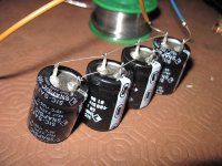
Proper observations the yours, as I had just compared Non-Polar vs No Cap: so I finally compared a bank of polars equal to 272uF/400V against the back-to-back 235uF/400V: the change of capacitors really does have an audible effect which I can translate as a minor listening fatigue, as stated before.
Thanks guys, now I'm firmly convinced that is not a placebo effect!
Attachments
Why? You are pulling this out of the blue with no justification at all.The additional back-to-back NP big size capacitor acts as favourite path of AC signal.
The only "favourite path" will be the one with the least AC impedance, basically capacitance based impedance plus ESR .
By the way, never measured it, but I guess ESR in a reverse polarized capacitor shouldn't exactly be good, you are using it the opposite way it was intended to.
Now if all your justification is "reduced listener fatigue" or similar mumbo jumbo, please be free to also file it in the large Placebo Effect drawer.
If you want to get a better "favourite path" , do it the right way: start by pulling that reverse biased useless/annoying capacitor from the power supply and continue by wiring it back, but in parallel with the other one, and with proper polarity.
Hey!!!, I'm quite certain that *measurable* (instead of imagined) results will be found.
They might also be *audible* ,of course 😉
Thanks guys, now I'm firmly convinced that is not a placebo effect!
That is, however, still completely consistent with it's in fact being a placebo effect.
Chris
The additional back-to-back NP big size capacitor acts as favourite path of AC signal.
Why? You are pulling this out of the blue with no justification at all.
I've to admit, probably you're right. My sentence cannot be proved. It's my guess that is only the polar capacitor which better acts as a component that stores and delivers energy in a DC circuit, while the NP ones do their better job in AC circuits as signal coupling, low pass and noise filters. I have never seen my "useless/annoying" NP capacitor as a power storage component due to the presence of the reversed cap.
Now if all your justification is "reduced listener fatigue" or similar mumbo jumbo, please be free to also file it in the large Placebo Effect drawer... if you want to get a better "favourite path" , do it the right way: start by pulling that reverse biased useless/annoying capacitor from the power supply and continue by wiring it back, but in parallel with the other one, and with proper polarity.
That are my listening tests I've done so far:
1) without my "useless/annoying" NP capacitor
2) installing my "useless/annoying" NP capacitor, shorting the bottom cap, so practically adding a 470uF/400V polar cap to power supply
3) installing my "useless/annoying" NP capacitor
4) installing my "useless/annoying" NP capacitor with a security diode on the bottom cap
5) disassemble my "useless/annoying" NP capacitor and install the two caps in the correct polarity, so practically adding a 940uF/400V polar cap to power supply
6) get rid of my "useless/annoying" NP capacitor, and install a polar capacitor bank with capacitance nearly equal to the NP capacitor, i.e. 235uF/400V
I repeated the tests twice.
It is not a placebo effect if I really found solution 3) the very best for my ears which brings the musical performance back to life.
That's just your presonal preference, nothing wrong with that, but it also does not prove anything - certainly not to the tough crowd here...😀It is not a placebo effect if I really found solution 3) the very best for my ears which brings the musical performance back to life.
You could try a CCS fed shunt reg. The high impedance current source is in series with the PS and the shunt device provides a low impedance signal return.
Black gate did the bipolar electrolytic over 20 years ago and your just finding it now?
Tradition says that knights were errant on the quest of the Holy Grail since many years after the death of Christ.
"NH Type
Non-polar types with high voltage AC operation in mind, extended up to 350 volt. This allows them to be used in power supply applications where the ultra low loss and other characteristics revolutionize power supply design and performance. Please note Black Gate production ceased in 2006 so these capacitors are very hard to get hold of."
I'm not frustrated to having found today something magical and pleasant that makes me happy, which was already invented and used since many years.
I'm much more angry and irritated when people affirm that this is just a placebo effect. I am the first, after many years of experience in this field, who knows very well the risks of placebo effects on electronic components-rolling. To avoid this I usually do blind listening test, with a switch which my wife turns randomly and suddenly. In this case my tests were not blind due to the high dangerous voltages in place and were not immediate due to the fact I had to discharge the capacitors and turn off the machine before the following test. But I've repeated them many times, with always the same result.
Thanks for your input, I have just found someone who had the same idea here (not in power supply but as cathode bypass), and I'm looking forward to find others about NH caps!
I also want to use a 220uF 100v Black gate NH series at C13. Any comments?
http://www.diyaudio.com/forums/tubes-valves/198575-black-gate-wkz-can-they-used-these-circuits.html
I will keep you posted when found someone already using NH caps in DC power supply.
Last edited:
New Blackgate replacements coming from Audio Note UK in 2016. They have a slightly lower build level bipolar series already. The Blackgate replacements will unlikely be outrageously expensive ( Audio Note owner is notorious for high prices)
Audio Note
Audio Note
Last edited:
- Status
- Not open for further replies.
- Home
- Member Areas
- The Lounge
- My Holy Grail of amplification found: Non-Polar electrolytic caps across power supply