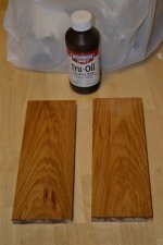
Here are the side pieces for my preamp.
I picked up 24 sq. ft. of 3/4" x 6" unfinished hickory hardwood flooring on clearance for $10.
They are tongue n' groove which is nice since I will be flush mounting aluminum on the top of the chassis.
This stuff is beautiful.
I'm just going to finish it with gun stock oil and wax.
Final outside dimension of my preamp chassis will be 8.75" x 12".
Attachments
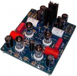
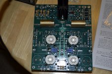
here are some pics from my aikido built
no noise, no hum
its a second one, frienkly, soundwise I preffer the octal one
Audio Pages: Aikido 5687 linestage
no noise, no hum
its a second one, frienkly, soundwise I preffer the octal one
Audio Pages: Aikido 5687 linestage
Next question.....My kit showed up today.
I want to run my 6CG7's @ 10mA correct?
I need to be sure to configure my RC circuit properly.
I want to run my 6CG7's @ 10mA correct?
I need to be sure to configure my RC circuit properly.

C4 Quandry
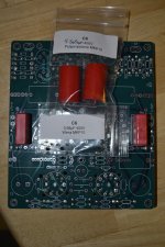
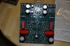
So......I have two baggies with C6 on them.
One is a pair of .68uF WIMA's and the other is a pair of 4.7uf Audiophilers.
I placed the WIMA's @ C6 where the silk screen has a nice rectangular space for them, is this correct?
Are the 4.7's really supposed to be for C4? It looks like there is ample room for them.
Attachments
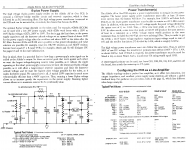
What's the schematic show?
Try to find were the 1uf/4.7uf goes vs the .68uf.
I would have to find your schematic but I would imagine those 1uf/4.7uf coupling caps would be close to the grids of your tubes.
Try to find were the 1uf/4.7uf goes vs the .68uf.
I would have to find your schematic but I would imagine those 1uf/4.7uf coupling caps would be close to the grids of your tubes.
I did not receive a baggie labeled C4 and C4 says its for power supply bypass I believe ( I'm at work now so I can't say for certain.)
WONDERFUL!!!!
Thank you soooo much!
I feel like a tard now, I didn't even think about looking for Aikido pictures.
LOL
Thank you soooo much!
I feel like a tard now, I didn't even think about looking for Aikido pictures.
LOL
I know John messed up some of his kits, because he cut and pasted the PSU from one project onto the main circuit from another, so sometimes you get things like this.
The wima caps will be something in the PSU. The 1uF/4.7uF would be the coupling cap (there is only one coupling cap in the signal path, or maybe two if that board has two outputs, as some aikido boards do). Can you post pics of the pcb from the top showing the whole lot, along with a photo of the schematic from the manual. Then we should be able to figure it out.
The wima caps will be something in the PSU. The 1uF/4.7uF would be the coupling cap (there is only one coupling cap in the signal path, or maybe two if that board has two outputs, as some aikido boards do). Can you post pics of the pcb from the top showing the whole lot, along with a photo of the schematic from the manual. Then we should be able to figure it out.
The picture that Globug posted is exactly what I ordered and those two red round caps are the ones in question.
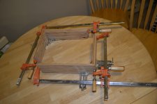
All is well for the time being.
I have more 96/4 and I'm ready to melt some metal.
All is well for the time being.
I have more 96/4 and I'm ready to melt some metal.
Attachments

Last edited:
Now I'm wondering what value I use for R17.
I have 10, 20, 100, 200 & 470 all 1W.
I don't see in the manual where it discusses the R17 value other than 100 to 1k.
I have 10, 20, 100, 200 & 470 all 1W.
I don't see in the manual where it discusses the R17 value other than 100 to 1k.
with Broskie I find that questions are often answered with another question
many questions I couldnt find a clear answer to
the sole reason I havent built one yet
but good to see you are having a go at it
many questions I couldnt find a clear answer to
the sole reason I havent built one yet
but good to see you are having a go at it
It appears that many of the variable value parts are tagged "This value takes experimenting.".
With this in mind I just guessed 470Ω for R17 since it was close to the middle of 100 & 1k.
I hope I don't blow anything up.
This may get powered up by Friday.
It all depends on how chassis building goes.
With this in mind I just guessed 470Ω for R17 since it was close to the middle of 100 & 1k.
I hope I don't blow anything up.
This may get powered up by Friday.
It all depends on how chassis building goes.
Yes, pay close attention to what is in the bags versus what they are labeled...I have found many mis labeled bags in the kits....
Those 4.7uF caps are for the in coming B+ bypassing the electrolytics - not the coupling caps.
Those 4.7uF caps are for the in coming B+ bypassing the electrolytics - not the coupling caps.
- Status
- Not open for further replies.
- Home
- Amplifiers
- Tubes / Valves
- My First Tube Preamp