lomtik,
I would recomend PCB over p2p for chip amps, PCB is to much easier 🙂 If you want, there was a thread that was pretty popular up until about last week descussing the differences between PCB and P2P in the chip amp section. I built the 3875, and now the 3886, I prefer the sound of the 3886 and snubber vs the 3875 with regular psu. But that was during the innitial testing, thinking about how good the 3886 and snubber could sound.
There are some on the forum that prefer on over the other, but I'd say they are about even.
homer09, did you check out PD's rev C boards in the market place section with the gold traces? They look really nice.
Thanks,
Josh
Thanks for your comment,
I've added another question about the transformer, while you were answering. 🙂
So, LM3886 is better for 4ohm, but is it still good for 8ohm? I haven't decided yet which speakers I am going to use. I have 4ohms at home right now connected to a stereo system, but might consider something else later on.
Sure, building both might be great as well 🙂 but I might just get one kit and build the socond one just on a protoboard.
That was my second part of question. I ment PCB VS regular protoboard. Will it be still ok to go without PCB?
Sorry for confussing you. 😕 I'll edit my original post as well to avoid others getting confused as well
😀
m0tion said:Just built one of the snubber power supply boards and it seems like an extra 10uF/50V cap was included with all of my power supply stuff, any idea why?
No.. but i got an extra too, I'm trying to figure out what it's for.
As for a Transformer, you're kind of screwed there. All the best more powerful units are pricey. So if you know you don't want alot of power, you can get away with a lower rated one. Personally I want to go deaf so i got a 330VA tran.
Sorry for the lack of response. I am currently in Philadelphia on an unexpected visit to see my ill grandmother (not doing well with lung cancer). I had meant to spend the weekend working up an instruction manual for the new LM3886 kit. Here is a description of the components:
Board pic:
http://www.briangt.com/gallery/lm3886amp/3886_019?full=1
Amp board:
R1 - input resistor = 1k (2 - black on the resistors packed)
R2 and Rf - input-to-ground resistor = 22.1k (4 - uncolored)
R3 - feedback-to-ground resistor = 681 (2 - blue)
Rm - mute resistor = 10k (2 - red)
picture of 2 ways to wire feedback resistor:
http://www.briangt.com/gallery/lm3886amp/3886_037
with and without the feedback capacitor, notice the resistor placement
C1,C2,Cm - 100uf
C3,C4,Cz - 0.1uf
Ci - 47uf
Power supply board:
R1,R2 - 1 ohm resistors for snubber network
R3,R4 - 2.2k bleeder resistors for power supply caps (mount on bottom)
R5 - 10k or 22k resistor for LED (10k might be too bright, so try 22k to lower the current supplying the LED to reduce brightness)
C1-C4 - snubber caps = 0.1uf
C5,C6 - power supply caps = 10,000uf
C7 - 10uf cap for LED (extra included in bag with diodes)
D1-D8 - power supply diodes = MUR860
I will be back in town tomorrow (monday).
As for the kit status, all of the US LM3886 kits and PS-kits received up to last wednesday (23rd) were shipped out. For the international orders, 2/3 of the LM3886 kits were shipped out, and I will work on getting the remaining shipped out ASAP. I will receive the new LM3875 boards in the mail on Monday, and the new LM4780 boards by the end of the week/early next week.
Drop me e-mail if you have any more questions. I am sorry that I haven't been able to post the manual yet. It is near the top of my list. I haven't had e-mail access since Friday, and not much more time on the computer tonight, so I will spend time tomorrow night catching up on mail.
--
Brian
llmobll said:As for a Transformer, you're kind of screwed there. All the best more powerful units are pricey. So if you know you don't want alot of power, you can get away with a lower rated one. Personally I want to go deaf so i got a 330VA tran.
Go death with this amp? Is it that great? 😀 *felling all happy*
m0tion said:Just built one of the snubber power supply boards and it seems like an extra 10uF/50V cap was included with all of my power supply stuff, any idea why?
llmobll said:
No.. but i got an extra too, I'm trying to figure out what it's for.
I included an extra 10uF cap with all of the power supply packs, as I pre-packed all of the diode bags with 8 - MUR860 and 2 - 10uf caps for the LM3875 and LM4780 kits, which use the 8 and 2 combination. I reused the same bags the new power supplies to save the amount of items that I had to pack at a time. Please don't be confused, as there is purposely an extra cap with the kit.
--
Brian
llmobll said:On Brians site he has a picture of using both, from the layout it looks as if one bypasses a cap, while the other uses it?? I don't know what I should do?
This little trick was my idea and I thought it would be a convenient way to avoid jumpers on a board accomodating both options (cap and no cap).
lomtik said:And final question is about transformer. The recommended one is about $50US, so the final price will be around 80CAD with shipping to Toronto. That alone is well above kit's price. Are there any other cheaper versions and how bad are they compared to recommended model?
If that helps, A-1 Electronic Parts (http://a1parts.com/) and Active Surplus are the stores that are close to my home and work, so it would be best to pick up from there.
The transformer is important for sound quality. So far the best transformers I tried with GC are coming from Plitron (they are located in Toronto). Also, A1 electronic has sometimes suitable surplus transformers (also from Plitron) at very reasonable prices ($20 -30).
lomtik said:Thanks for your comment,
I've added another question about the transformer, while you were answering. 🙂
So, LM3886 is better for 4ohm, but is it still good for 8ohm? I haven't decided yet which speakers I am going to use. I have 4ohms at home right now connected to a stereo system, but might consider something else later on.
Sure, building both might be great as well 🙂 but I might just get one kit and build the socond one just on a protoboard.
That was my second part of question. I ment PCB VS regular protoboard. Will it be still ok to go without PCB?
Sorry for confussing you. 😕 I'll edit my original post as well to avoid others getting confused as well
😀
For transformer, Piltron's are probably the best, as Peter recommended, but if you're like me and looking for a more budget oriented buy, check out www.partsconnexion.com . since they ship from canada, you will save there. they have some good hammond transformers, im probably going to buy the 182PP2, 225VA 22V.
If there is a possibilty you would want to drive 4 ohmers, get the lm3886, safest call and your probably not sacrificing anything.
PCB vs protoboard... PCB is just so much easier to build, less possibilities of mistakes, better ground planes, shorter traces, cleaner finish...
Hmm, just tested my PS board and I get the correct DC voltage on the outputs (I'm using a 22VAC transformer and I get +/- 30VDC on the outputs respectively), but my LED doesn't light up at all. I double checked all of the solder joints with the LED, resistor, and capacitor near it an all seems to be in order. I attached the LED with the longer lead (anode right?) facing the diode section of the PCB. Nothing smoked and the LED still appears to be intact interally so I don't think I got the polarity mixed up. Two resistors came in the kit for use with the LED and I chose the GOLD-BLACK-BLACK-RED-GOLD one (reading the colors off the LED to the best of my ability).
Peter Daniel said:The transformer is important for sound quality.
I know it's inconvenient in terms of fitting in a normal height chassis, but have you tried a quality EI core transformer? A toroid is not the best option other than it has low radiated EMI. If you can find an EI that's mechanically quiet and keep it away from the audio circuitry, I believe it would be the best way to go. I don't think the original Gaincard used one because they were being cheapskates!
Another thing that I want to try with a chip amp is full wave rectification with a center-tapped transformer. You need two transformers (or two CT secondary windings on one core) to make a +/- supply and the windings are of twice the voltage required for the usual full wave bridge implementation, but you have four fewer diodes making noise and a lower forward voltage drop. You can also use some additional tricks to cut common mode noise on the secondary of the transformer.
It would be easy to try with two of the normal toroids used (one each for the +/- supplies) - you just use the secondaries in series to create a CT and get the 2x voltage required.
edjosh23 said:lomtik,
homer09, did you check out PD's rev C boards in the market place section with the gold traces? They look really nice.
Thanks,
Josh
Yes, i did see them, but i already had a comitment to brian's version. Yes they do look very very nice. But, im not sure if sonically they will sound different with the same components. I think their advantage is that Peter is packaging them with some excellent components, which will make the real difference.
homer09 said:
Yes, i did see them, but i already had a comitment to brian's version. Yes they do look very very nice. But, im not sure if sonically they will sound different with the same components. I think their advantage is that Peter is packaging them with some excellent components, which will make the real difference.
I agree, but the gold does look nice, and I'm guessing costs a little extra too.
For the past hour I had my amp connected to my 8ohm 100w dummies. With the volume hald way, the dummies get wayyyy too hot to touch. The past week I've been unable to give the amp a good burn in, like I just did. I'm going to let it burn in for another half hour or so and listen for a difference.
m0tion or llmobll, any updates on the amp?
Thanks,
Josh
Hmm, just tested my PS board and I get the correct DC voltage on the outputs (I'm using a 22VAC transformer and I get +/- 30VDC on the outputs respectively), but my LED doesn't light up at all. I double checked all of the solder joints with the LED, resistor, and capacitor near it an all seems to be in order. I attached the LED with the longer lead (anode right?) facing the diode section of the PCB. Nothing smoked and the LED still appears to be intact interally so I don't think I got the polarity mixed up. Two resistors came in the kit for use with the LED and I chose the GOLD-BLACK-BLACK-RED-GOLD one (reading the colors off the LED to the best of my ability).
I'm going to get this resolved before proceeding. Any ideas?
jeff mai said:
I know it's inconvenient in terms of fitting in a normal height chassis, but have you tried a quality EI core transformer? A toroid is not the best option other than it has low radiated EMI. If you can find an EI that's mechanically quiet and keep it away from the audio circuitry, I believe it would be the best way to go. I don't think the original Gaincard used one because they were being cheapskates!
Another thing that I want to try with a chip amp is full wave rectification with a center-tapped transformer. You need two transformers (or two CT secondary windings on one core) to make a +/- supply and the windings are of twice the voltage required for the usual full wave bridge implementation, but you have four fewer diodes making noise and a lower forward voltage drop. You can also use some additional tricks to cut common mode noise on the secondary of the transformer.
It would be easy to try with two of the normal toroids used (one each for the +/- supplies) - you just use the secondaries in series to create a CT and get the 2x voltage required.
Actually I tried both. The EI transformers maybe weren't the best quality, but they looked definitely well made, with flat magnet wire. They were definitely worse sounding than Plitron.
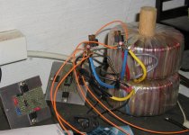
In the pic is my setup for your second suggestion (made also with Plitron transformers) it sounded slightly different than a single toroid, I thought it was better, but only marginally. I did those tests almost a tear ago, so it may be a good idea to refresh my memories. Maybe this time I will come to different conclusions😉
Attachments
m0tion said:
I'm going to get this resolved before proceeding. Any ideas?
Do you get a voltage across the led holes on the PCB? maybe bad LED if you do.
Peter Daniel said:Actually I tried both. The EI transformers maybe weren't the best quality, but they looked definitely well made, with flat magnet wire. They were definitely worse sounding than Plitron.
In the pic is my setup for your second suggestion (made also with Plitron transformers) it sounded slightly different than a single toroid, I thought it was better, but only marginally. I did those tests almost a tear ago, so it may be a good idea to refresh my memories. Maybe this time I will come to different conclusions😉
Peter,
You always impress with the breadth of stuff you try. I should have known you'd already tried these things!
An EI transformer should let much less junk come through the AC than a toroid. There must be other factors that come into play.
If you try the full wave / two transformer idea again, try a snubber at the transformer secondary and also a couple of small (47nf) caps from the secondary +/- to the CT (which is GND in a full wave circuit.) I think this will provide some benefit without interacting with the PSU caps on the other side of the diodes.
I'm going to try your 100uf BG N caps tweak as soon as I place my next order with MP or Parts Connexion!
I measure 30V across the LED, 10V from the anode to PG+, and 40V from the cathode to PG+. Bad LED?
m0tion said:I measure 30V across the LED, 10V from the anode to PG+, and 40V from the cathode to PG+. Bad LED?
30V

LEDs are supposed to be operating at ~3V.... something is wrong here, any led u put into that circuit will blow. recheck everything!
Ok, this is kind of embarressing, but I've been over the board a couple of times. No cold joints, all component values and placement seem correct, all polarity seems correct. I get +/- 30VDC on the respective outputs. Voltage before D9 measures 10VDC, after D9 it measures 40VDC. Across the LED I get 30VDC (dropping from 40V to 10V across the LED). The LED doesn't light up, but still appears to be intact. Included below are pictures. Any advice appreciated.
Image 1
Image 2
Image 3
Image 1
Image 2
Image 3
m0tion said:Ok, this is kind of embarressing, but I've been over the board a couple of times. No cold joints, all component values and placement seem correct, all polarity seems correct. I get +/- 30VDC on the respective outputs. Voltage before D9 measures 10VDC, after D9 it measures 40VDC. Across the LED I get 30VDC (dropping from 40V to 10V across the LED). The LED doesn't light up, but still appears to be intact. Included below are pictures. Any advice appreciated.
Image 1
Image 2
Image 3
And you're sure about the polarity of the LED?
- Home
- Amplifiers
- Chip Amps
- my first try at a LM3886 layout, any comments/suggestions?