looks vey good
now you can test your amplifiers
and get some comment to different resulting waves
there are experienced persons here
that can tell what this or that SQUAREWAVE indicates
by the way
you should have some SquareWave test signal built in,
in your oscilloscope, too
------------
I have one separate Function Generator (square, triangle, sinus & sweep) at all kinds of level & frequency.
It is one cheap one. ( Taiwan or HongKong made )
But has not only SWEEP but also DC-Offset setting.
The output Impedance is Zout = 50 Ohm BNC
So it works best into lower impedance load.
I use one 56 Ohm resistor in parallel with amplifier input.
Even if Ouput connectors are BNC,
I use one BNC to RCA adapter for use of normal Audio RCA signal cables.
lineup said:looks vey good
now you can test your amplifiers
and get some comment to different resulting waves
there are experienced persons here
that can tell what this or that SQUAREWAVE indicates
by the way
you should have some SquareWave test signal built in,
in your oscilloscope, too
------------
I have one separate Function Generator (square, triangle, sinus & sweep) at all kinds of level & frequency.
It is one cheap one. ( Taiwan or HongKong made )
But has not only SWEEP but also DC-Offset setting.
The output Impedance is Zout = 50 Ohm BNC
So it works best into lower impedance load.
I use one 56 Ohm resistor in parallel with amplifier input.
Even if Ouput connectors are BNC,
I use one BNC to RCA adapter for use of normal Audio RCA signal cables.
a 50 ohm load is only really needed if you want clean square waves. i have a function generator that has a range of 0.1hz-5Mhz, also with a 50 ohm output the sine wave function is ok for checking an amp for functionality and full power output, but since it is a triangle wave that has been through a wave shaper, it has little blips on the peaks, so it's not a low distortion sine wave. for low distortion testing, i'm building a wein bridge oscillator. i have the transistors and the light bulb, and just found a 4 position switch yesterday (it pays to keep those "junk" items like a 4/1 phone line/ modem switch) in a suitable box, no less. i've got a 100k dual pot around here somewhere, and i'm sure i can find the caps. i think i'll run it off of dual 9V batteries. or, i'll run it off of a line powered supply, and make it part of another piece of test equipment i've designed, an output impedance test box.
yes,
I have noticed
the 50 Ohm load is not very critical, at least for sinus testsignal
And connector RCA + Audio cable.
For higher speed squarewave may be different
Then we can use
connector BNC + 50 Ohm Coaxial cable + Termination ~ 50 Ohm
... I think
I have noticed
the 50 Ohm load is not very critical, at least for sinus testsignal
And connector RCA + Audio cable.
For higher speed squarewave may be different
Then we can use
connector BNC + 50 Ohm Coaxial cable + Termination ~ 50 Ohm
... I think
now amp test
dear all,
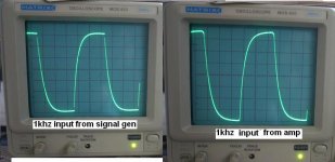
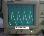
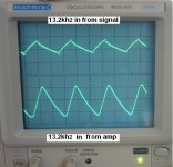
i just tested my aleph-3 amp. here i show the result. i am new to oscilloscope so i can be wrong.
some test result with 20hz, 500hz, 1khz, 13.2khz, all looks to me is ok but confused about 20htz.
pls note that i off the camera flash light so there can be seen flikers line on the screen.
dear all,
i just tested my aleph-3 amp. here i show the result. i am new to oscilloscope so i can be wrong.
some test result with 20hz, 500hz, 1khz, 13.2khz, all looks to me is ok but confused about 20htz.
pls note that i off the camera flash light so there can be seen flikers line on the screen.
Attachments

now you can do test
have test signals. all kinds of
as i told you,
you should learn now,
what these not perfect squarewaves will tell about your amplifier
there should be some tutorial with different images of wavwforms
with an explanation
but you will get it soon from members here, too
========================
About my poor 2 MHz scope.

http://www.bcae1.com/repairbasicsforbcae1/repairbasics.htm
have test signals. all kinds of
as i told you,
you should learn now,
what these not perfect squarewaves will tell about your amplifier
there should be some tutorial with different images of wavwforms
with an explanation
but you will get it soon from members here, too
========================
About my poor 2 MHz scope.
The second photo is the same signal displayed on a Tektronix 5110 oscilloscope rated for 2MHz (not a misprint, 2MHz).
Although the 2230 has slightly better resolution, the 5110 has good enough resolution for virtually any problem that you'll encounter.
The signal is a 160kHz square wave.
This is typically the highest frequency you'll find in the audio section of most class D amps.
http://www.bcae1.com/repairbasicsforbcae1/repairbasics.htm
Hello Michael.
I have been having a look at your pictures. Erm !!!
No matter, what the input signal looks like from the generator, the output from the amp should be similar.
To be honest, the "risetimes" are nowhere near high enough for squarewave testing, but you can still learn a lot about how to test.
Post 16 and 27. Why does the signal from the generator look so different. When you connect the generator to the amp does the waveform from the generator change. Signal generators usually have a little output stage of their own. Are you using the signal straight from the PIC. Even an emmitter follower would help. The output from the amp in #27 looks almost like it is clipping, and the signal has hit the rails.
You do need to read up on all this -- it's too vast a subject to put it into posts like this --- but we can help Michael with any questions you have.
And I wish I knew how to program a PIC like that 🙂
yes, i have to do more testing the signal from generator. i did added just 0.1uf cap onto the pic output. i believe there is some problem with signal. anyway it is just a begining. There are lots to be learn....ha...this is the first time i ever touched oscilloscope.
thaks for your answer. i can realise signal generator have some problem that the signal is cliping.
thaks for your answer. i can realise signal generator have some problem that the signal is cliping.
A 0.1 mfd cap will act as a differentiator. It's cutting all the Bass out. Make sure you don't overdrive the amp's. Dont test at more than a couple of watts output to begin with.
hi mooly,
thaks, i found it's a probe problem. my oscilloscope dsn't comes with proble so i made as like this.
http://www.cromwell-intl.com/radio/probes.html
my cable is 2mtr.
i just tested and found my signal was distorted by this probe. i made 10x type. is there anyway i can make 10x probe?
thaks, i found it's a probe problem. my oscilloscope dsn't comes with proble so i made as like this.
http://www.cromwell-intl.com/radio/probes.html
my cable is 2mtr.
i just tested and found my signal was distorted by this probe. i made 10x type. is there anyway i can make 10x probe?
There are probes that are good for RF testings.
RF = radio frequency
There are probes that are better for AF.
AF = audio frequency
There are probes that will fit the best for HF.
HF = high frequency (not the same as VHF = very high freq)
The common for all rpobes
is that there is one small adjustable capacitor,
to set the high frequency behavior of the test pin.
----------
This page, as was posted, is a good one:
http://www.cromwell-intl.com/radio/probes.html
Shows how you can build your own correct probe.
Of course, if you buy one probe from some electronical company
it would be best.
They are not too expensive. But very useful.
regards lineup
space2000 said:confusion about 20htz
your 20hz waveform is being differentiated through an RC network that has a cutoff frequency of about 200hz. everything 200hz and above will look normal, everything below 200hz will begin to look like your picture. the amp is clipping, so it cuts off the peak of the waveform.
lineup said:There are probes that are good for RF testings.
RF = radio frequency
There are probes that are better for AF.
AF = audio frequency
There are probes that will fit the best for HF.
HF = high frequency (not the same as VHF = very high freq)
The common for all rpobes
is that there is one small adjustable capacitor,
to set the high frequency behavior of the test pin.
----------
This page, as was posted, is a good one:
http://www.cromwell-intl.com/radio/probes.html
Shows how you can build your own correct probe.
Of course, if you buy one probe from some electronical company
it would be best.
They are not too expensive. But very useful.
regards lineup
look up a better schematic for a probe.... look up "compensated scope probe" . compensated probes have a variable cap across the probe tip resistor that allows you to adjust the probe for proper frequency response by compensating for the capacitive loss of the cable. the compensation cap is usually a 50pf trimmer inside the probe body or BNC connector body. the probe tip resistor in a usual probe is 10MEG with a 1MEG across the cable, and the trimmer cap goes across the 10MEG. some tektronix probes have a pair of metal sleeves as part of the probe body that are adjusted by threads that make the probe longer or shorter.
Hi Michael,
You don't need anything fancy to start.
http://cpc.farnell.com/IN04468/test-equipment/product.us0?sku=unbranded-10ha080
A proper divide by 10 probe will have a little trimmer cap in it to compensate for different 'scope input capacitances.
Just use a lead like the above for now. It's absolutely fine for what you need to start.
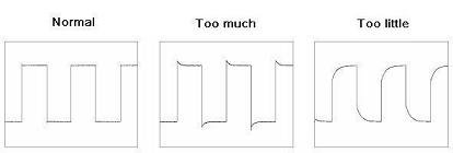
Probe calibration:
Calibrating probe isn’t hard task especially when oscilloscope has necessary tools built in. This is a signal generator used for calibration. Turn on signal generator on oscilloscope and put tip to it and ground clip to oscilloscope ground. There should be some sort screw for adjustments in the compensation box of probe. By inspecting signals in oscilloscope you can compensate probe.
Overcompensated or under-compensated probes may produce significant errors in rise time and amplitude.
here is the pic..
i found this at
http://www.scienceprog.com/oscilloscope-probes-for-accurate-signal-measurements/
mine 1khz signal showing is "Too little".
Attachments
hi mooly,
yes, it is probe problem. i made this probe. http://www.cromwell-intl.com/radio/probes.html
its has to add cap like 10pf or more, now need to know what value should be add. i tried with 13.3pf but still a bit low showing.
is there any pot for cap? like resister have pot.
yes, it is probe problem. i made this probe. http://www.cromwell-intl.com/radio/probes.html
its has to add cap like 10pf or more, now need to know what value should be add. i tried with 13.3pf but still a bit low showing.
is there any pot for cap? like resister have pot.
- Status
- Not open for further replies.
- Home
- Amplifiers
- Solid State
- my first oscilloscope