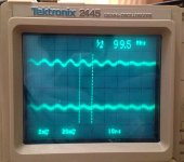
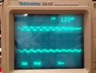
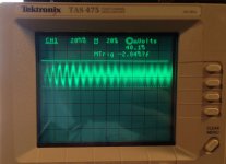
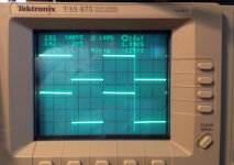
So given all the problems I've encountered with my previous power supply design, I tried something different. It's based around 317/337 rather than 78/7912, and I incorporated several ideas from everyone's posts and a couple from application hints in their respective datasheets. The result is much better; 1.2mV ripple @ nearly 100MHz. I have scope shots of the power supply in action, but not of the actual amp yet. I heard a very small, nearly indistinguishable difference in noise (mostly at low volume levels) when listening to the amp with the new power supply, but it's nice to know that it's performing much better. This time around I used all new components, instead of using recycled components in my previous PS. The 470uF caps in parallel rather than a single 1000uF function to achieve lower ESR, and I decided to use trim pots instead of regular 1% films for the Adj resistor to get the exact voltage I needed. I was reluctant about the two 0.1uF caps before the rectifier bridge, but I can't see it hurting, and the transformer is much larger and higher quality than the previous one I'd used. I also decided to change the voltage to ±15V rather than ±12V since it's the voltage used to obtain all the measurements in the op-amp and buffer data sheets. Overall I'm satisfied for now, and hopefully, when I finish the PCB design, things will improve even further, since right now it's constructed on Veroboard.
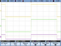
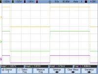
P.S. CH2 shows 20mV/div rather than 2mV/div because for some reason this scope doesn't distinguish between 1X and 10X probes on CH2.
P.S. CH2 shows 20mV/div rather than 2mV/div because for some reason this scope doesn't distinguish between 1X and 10X probes on CH2.
Attachments

Last edited:
So given all the problems I've encountered with my previous power supply design, I tried something different. It's based around 317/337 rather than 78/7912...
You can go up to 22uF for C9 and C10. Just solder another 10uF in parallel with each one you already have. There is an old but rather well quoted analysis done by Errol Dietz in ED. Up to 22uF gets better, after that little additional improvement. Here is another good 317/337 noise analysis for you to skim through if you want:
Simple Voltage Regulators Part 1: Noise - [English]
If you want to go for some extra credit DIY work, follow those 317/337s with a LT1963A/LT3015 pair for even lower cascaded ripple and noise. Set your LM317/337 "pre-regulators" for at least a volt more than your output, so +/-16Vdc if you are shooting for +/-15Vdc out of the LDOs, which leaves a volt across the LT LDOs. Sergey888's circuits would do something similar for less $$$. 🙂
Last edited:
You can go up to 22uF for C9 and C10. Just solder another 10uF in parallel with each one you already have. There is an old but rather well quoted analysis done by Errol Dietz in ED. Up to 22uF gets better, after that little additional improvement. Here is another good 317/337 noise analysis for you to skim through if you want:
Simple Voltage Regulators Part 1: Noise - [English]
If you want to go for some extra credit DIY work, follow those 317/337s with a LT1963A/LT3015 pair for even lower cascaded ripple and noise. Set your LM317/337 "pre-regulators" for at least a volt more than your output, so +/-16Vdc if you are shooting for +/-15Vdc out of the LDOs, which leaves a volt across the LT LDOs. Sergey888's circuits would do something similar for less $$$. 🙂
Thanks for the link, very helpful!
You aren't going to believe this...but I have some LT3015s (as well as some TL431Bs to give them a fair try) in the mail, due to arrive Friday! I'll definitely give it a shot.
So you are seeing 100MHz just on the new PSU with no amp attached ?
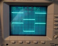
Try what I suggested at first, shorting the probe and then touching the shorted tip on the ground line of the supply.
Also does the oscillation disappear completely when you pull the mains plug on the supply. If so, then when you pull the plug does it stop instantly or fade away as the rails collapse. (you must fully remove the mains connection for this test, turning off a single pole switch in the primary doesn't fully isolate things).
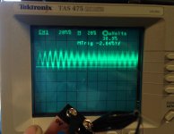
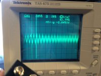
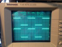
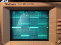
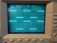
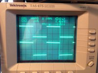
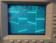
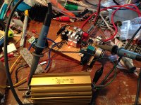
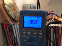
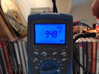
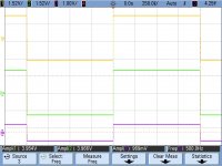
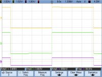
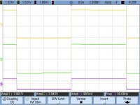
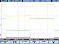
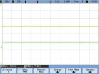
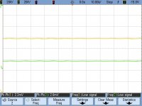
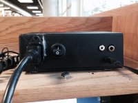
I think there's either something wrong with my scope, testing method, or something in the environment out of my control. I've tried everything that's been suggested, so I decided to look at a 9V battery and my adjustable bench power supply. Guess what....I got the same results on the battery and power supply I've been getting with my power supply for the headphone amp. I'm stumped, and I've decided it's good enough for now so I can focus on fixing other things with the actual amplifier.
Pic one is my power supply, and the last two are of the 9V battery.
Pic one is my power supply, and the last two are of the 9V battery.
Attachments
That is why I wanted you to short the probes out to see if you got a clean trace 🙂
Try shorting the input of the scope directly at its input socket.
Try shorting the input of the scope directly at its input socket.
Hi all, I have a pretty major update on my project! I've re-done much of my design; the changes with the biggest impact are the completely new power supply, changing to a 10K pot, and halving most resistor values, and tweaking the input capacitor value. The result is a major improvement in both subjective listening and objective testing. I've done about 10 hours of listening on the amp and I'm surprised at how much better it sounds. Overall, V. 2 is improved in all but two areas; low frequency response is worse than before, (both audibly and on the scope) and the voltage regulators, opamp, and buffers run hotter than before. I'm guessing the higher temperatures are due to changing to a ±15V supply rather than the previous ±12V supply. I've put some rather beefy (if not overkill) aluminum heat sinks on the 317/337s, and I'm looking for some to use on the buffers. Another possibility contributing to higher operating temps is that some oscillation is now occuring, as the component layout is very different from the previous layout, but I couldn't find any evidence of it oscillating. I'm not too worried about the higher temperatures, as they are well below the highest normal operating temperatures provided in the data sheets, and aren't "too-hot-to-touch" hot. Also worth noting is that the ambient temperature in my workspace hovers around 80F-85F.
I also tried experimented with different op amps; I tried OPA2227A, OPA2132PA, NJM4556AD, NE5532, LM4562, and AD8620. The 2227P I liked; it wasn't really an improvement per se, it just provided a slightly different sound that I liked. The LM4562 didn't agree well with my listening tastes. However, the rest sounded decent to good, and work just fine in the circuit. Personally, though, I prefer either the 2107 or 2227.
Pictures:
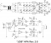
1. New schematic
2. Picture of the test setup during square wave testing on the scope with 40 ohm dummy load (yes, I'm one of those messy-desk people!)
3. Close-up of the amp
4. 100Hz; CH1 is the reference signal, CH2 is the amp's output. (note how screwed-up the output looks! Any ideas?)
5. 1kHz
6. 2kHz
7. 5kHz
8. 7.5kHz
9. 10kHz
10. 12.5kHz
11. 15kHz
12. 20kHz
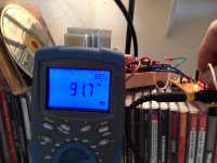
13. 317 temperature (in F) after listening for about 3hrs
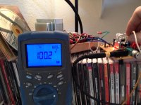
14. 337 temperature (in F) after listening for about 3hrs
15. OPA2107 temp ~3hrs
16. BUF634 left channel temp ~3hrs
17. BUF634 right channel temp ~3hrs
-Note that ambient temperature (in upper right-hand corner of DMM) is 82F.
-The headphones I were listening with were Shure SRH-840. (44 ohms-that's why I've chosen 40 ohms as my dummy load for scope testing. I plan on trying other values in the future to match some of my other headphones/IEMs.)
Sorry for the long post, and a sincere thank-you for you who've commented and helped me!
I also tried experimented with different op amps; I tried OPA2227A, OPA2132PA, NJM4556AD, NE5532, LM4562, and AD8620. The 2227P I liked; it wasn't really an improvement per se, it just provided a slightly different sound that I liked. The LM4562 didn't agree well with my listening tastes. However, the rest sounded decent to good, and work just fine in the circuit. Personally, though, I prefer either the 2107 or 2227.
Pictures:
1. New schematic
2. Picture of the test setup during square wave testing on the scope with 40 ohm dummy load (yes, I'm one of those messy-desk people!)
3. Close-up of the amp
4. 100Hz; CH1 is the reference signal, CH2 is the amp's output. (note how screwed-up the output looks! Any ideas?)
5. 1kHz
6. 2kHz
7. 5kHz
8. 7.5kHz
9. 10kHz
10. 12.5kHz
11. 15kHz
12. 20kHz
13. 317 temperature (in F) after listening for about 3hrs
14. 337 temperature (in F) after listening for about 3hrs
15. OPA2107 temp ~3hrs
16. BUF634 left channel temp ~3hrs
17. BUF634 right channel temp ~3hrs
-Note that ambient temperature (in upper right-hand corner of DMM) is 82F.
-The headphones I were listening with were Shure SRH-840. (44 ohms-that's why I've chosen 40 ohms as my dummy load for scope testing. I plan on trying other values in the future to match some of my other headphones/IEMs.)
Sorry for the long post, and a sincere thank-you for you who've commented and helped me!
Attachments
-
 10. 12,5kHz.jpg123 KB · Views: 66
 -
 09. 10kHz.jpg126 KB · Views: 45
 -
 08. 7,5kHz.jpg130.5 KB · Views: 52
 -
 07. 5kHz.jpg571.7 KB · Views: 60
 -
 06. 2kHz.jpg109 KB · Views: 60
 -
 05. 1kHz.jpg128.7 KB · Views: 66
 -
 04. 100Hz.jpg112.2 KB · Views: 82
 -
 02. amp up close.jpg581.9 KB · Views: 93
 -
 01. test setup.jpg245 KB · Views: 81
 -
 00-schematic.jpg566.8 KB · Views: 151


Sounds like you are having fun 🙂
As for the LF response, the only component than can cause that are the values of the 0.22uf coupling caps and the 51k input bias resistor. If you are using FET opamps such as the OPA's then you can go much higher with that resistor and without the penalty of any DC offset. The bjt types like the 5532 would probably give a significant DC offset as measured at the buffer output with higher values. That's because a small but significant current flows out of the input pins. If there is a a high value resistor in series (your 51k) then that current develops a voltage and that voltage is seen by the opamp as a valid input... result... it amplifies it as it would any other signal. Check it though with the 5532 vs the OPA2132.
0.22uf and 51k gives a -3db point of around 15Hz, so yes, pretty high really. You may disagree here, but why not try leaving it as it is and replacing those 0.22uf caps with a 2.2 or 4.7uf electroylitic.
Thanks for the response! I should have seen that I made a RC high pass filter before the input....oops. Thanks for catching what I didn't! As a test, I've put a 2.2uF cap in parallel with the 0.22uF cap and replaced the 51K resistor with 75K, and the -3dB point should be at ~900mHz now, and it sounds better. Still haven't had a chance to look at it with the scope as fall semester just started, and progress may be a bit slower from here on in.
EDIT: I forgot to mention I tried switching out the OPA2107PA for the OPA2227PA again, and the temperatures of the regs, op amp, and buffers were all only a couple of degrees higher than ambient-MUCH cooler than before. I don't know if the 2107 was doing something funny in my circuit and the 2227 just works better, or maybe I just had a bad 2107.
EDIT: I forgot to mention I tried switching out the OPA2107PA for the OPA2227PA again, and the temperatures of the regs, op amp, and buffers were all only a couple of degrees higher than ambient-MUCH cooler than before. I don't know if the 2107 was doing something funny in my circuit and the 2227 just works better, or maybe I just had a bad 2107.
Last edited:
That should be plenty low enough, and as you have found by listening, it really makes a difference to get down to the bottom octave.
Its not just roll off from a specific point that is the problem either, the roll off starting gradually and higher up the spectrum reduces the whole amount of LF energy... if that makes sense. Same if the top end rolls off a little. One or two db down at say 10kHz may not sound much but added up over the top octaves... a lot of energy is missing.
Excellent 🙂
I haven't forgotten about this project-I've just been very busy at school. I have worked on it a little more, and I think I've finalized my design, after showing it to a couple of my professors at school and some other students who are interested in audio.
There were only a few minor changes, but they helped a lot:
-Added 56uF bypass caps in addition to the 47nF caps that I already had
-Changed the op amp to OPA2132PA (side note: I had 15 or so people listen to it and I'd say 3/5 or 4/5 preferred the 2132 over the 2107, myself included; it tested better; ran cooler; and it's much cheaper!)
-Added a DPDT switch so I can switch gain (not my idea; I stole/borrowed the idea from RocketScientist's O2).
I'm in the process of designing a PCB for it; does anyone know of a good PCB manufacturer that will accept less than 5 qty boards? I can justify having 5 boards or so, but past that, it gets ridiculous to have that many and even more ridiculously expensive. I do have the ability to make 'DIY style' boards using a laser printer and ferric chloride, which I plan to use to verify the layout, but I would like a professionally made PCB for all the work I've put into it and the fact that I plan on using it at least a couple hours a day. Not to mention it will be double-sided and it's very difficult to do double-sided boards correctly with the 'DIY' method.
Afraid I can't help on the PCB's, I tend to always do my own as one offs. Its good getting people to actually listen and say which they prefer. One device worth trying could be the OPA2604 which is one of the more "coloured" sounding devices but coloured in the nicest way.
Read the last section on sound quality.
Read the last section on sound quality.
Attachments
does anyone know of a good PCB manufacturer that will accept less than 5 qty boards?
I use oshpark.com. You can upload gerber files. They also accept Eagle .brd files if you don't want to export to gerber.
Just to get this out of the way-sorry for the very long post.
It's been a long time since I've made an update-most can be attributed to being an EE student! In the last few weeks though, things have slowed down a bit, and I've been able to work on this project again. A few changes were made, but it's mostly (apart from the power supply) the same.
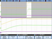
-The biggest change was the power supply. Instead of using 3-lead LM317 & LM337, I've changed to 5-lead LT1963A and LT3015A, like adgr mentioned earlier. I also changed the smoothing capacitors to 4 x 1000uF, Panasonic FM 35V, for their low ESR. The post-regulator caps are Panasonic FM now as well. Each of the 1000uF caps measured 0.12Ω-0.18Ω ESR, and the 220uF post-regulators measured between 0.19Ω-0.26Ω ESR. The generic caps I was using earlier measured 0.47Ω-0.73Ω ESR for the 470's, and the 220s measured 0.78Ω-1.22Ω ESR. PS ripple, as shown in the following scope pic (I get to use our school's Agilent 5014A DSOs now, what an awesome scope!) is less than 2.5mV per rail. It should be mention that I loaded the amp fairly heavily to get an realistic evaluation, and no matter what the amp's load was, it stayed this smooth the entire time. The bypass caps for the opamp and buffers are also Pana FM/35V. I'm very happy with the new power supply.
-I've recieved 15-20 new opamps to try out (thank goodness for TI's, AD's, and LT's student sample program....I've probably received $75-$150 just in samples in the last 6 weeks between the three companies.) This has also opened up lots of possibilities (and time testing them) so maybe performance can improve even more. Most notable Opamps were OPA827, OPA1611, OPA2211, LME49725, AD8599, ADA4004-2, AD8675, OP275 (note, not OPA275, it's a AD amp), LT1028, LT1056, LT1169, and LT1037. With the exception of the Linear Technology opamps and the OP275, which are DIP-8, everything from TI and AD are in SOIC-8. I ended up ordering a heap of BrownDog SOIC-8 to DIP-8 adapters so I can use them. I haven't gotten a chance to listen to many of them yet, but I really like the OPA827 and AD8599 so far. Also, I ordered an OPA2604AP like mooly suggested, and I do like how it sounds a bit. Thanks for the tip!
-A 15 pF cap between the inverting input and output has helped stability and reduced oscillation with more of the more "difficult", high slew-rate, high GBW opamps where phase change between output and inverting input was particularily high. It doesn't seem to change anything on the opamps I'd used previously without the caps.
-After being a professional (classical) musician for over 10 years, I've lost a lot of hearing in my left ear. I was a bassoonist, and the trumpets, trombones, and tuba sat directly behind my left ear. Percussion, even though the orchestra required plexiglass sound barriers, took quite it's toll too, so I decided to implement an easy to use and very effective L/R balance control, consisting only of a single element, 270deg. turn linear 1K pot. It's done wonders for my music listening, especially using IEMs.
-I removed the switchable gain. I found myself only using one setting, so removing the added complexity was a welcome change.
-I've also been working on a pocket sized version! It has a nearly identical amp circuit compared to the full-sized version, with the only changes being using 1/8W resistors, surface-mount opamps & buffers, deleting the output 6.35mm TRS jack, no L/R balance control, and deleting the power supply bypass caps. It also runs off ±8V instead of ±15V. The power supply is completely different, utilizing a TLE2426CLP voltage divider (which I normally don't like to use, but it's small and works well). The biggest problem was how I was going to implement battery power. I decided to use 2 7-cell 8.4V NiMH "9 volt" batteries, although I originally had planned on using LiPos. I wanted to be able to charge the batteries in the enclosure, so I designed a charging circuit small and simple enough to fit. It's just an LM317 in current-reg mode, a BC547 transistor, a couple resistors, a capacitor, and an LED to indicate charge status. It charges well, but at the time, the batteries can't be charged while the amp is in use. I'm working on a solution, but I don't have much experience with battery charging, so it may be trial-and-error until I figure things out. So far it sounds pretty close to the original, the most noticable changes are lower volume, a little bit more noise, and just a tiny bit less detail. It's still very much a work in progress however.
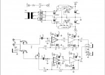
I've included the new schematics and a few scope pics to show how it's improved. Thanks for everyone's interest! And as per usual, I'm very open to suggestions/ideas for improvement, and any questions or concerns you may have.
It's been a long time since I've made an update-most can be attributed to being an EE student! In the last few weeks though, things have slowed down a bit, and I've been able to work on this project again. A few changes were made, but it's mostly (apart from the power supply) the same.
-The biggest change was the power supply. Instead of using 3-lead LM317 & LM337, I've changed to 5-lead LT1963A and LT3015A, like adgr mentioned earlier. I also changed the smoothing capacitors to 4 x 1000uF, Panasonic FM 35V, for their low ESR. The post-regulator caps are Panasonic FM now as well. Each of the 1000uF caps measured 0.12Ω-0.18Ω ESR, and the 220uF post-regulators measured between 0.19Ω-0.26Ω ESR. The generic caps I was using earlier measured 0.47Ω-0.73Ω ESR for the 470's, and the 220s measured 0.78Ω-1.22Ω ESR. PS ripple, as shown in the following scope pic (I get to use our school's Agilent 5014A DSOs now, what an awesome scope!) is less than 2.5mV per rail. It should be mention that I loaded the amp fairly heavily to get an realistic evaluation, and no matter what the amp's load was, it stayed this smooth the entire time. The bypass caps for the opamp and buffers are also Pana FM/35V. I'm very happy with the new power supply.
-I've recieved 15-20 new opamps to try out (thank goodness for TI's, AD's, and LT's student sample program....I've probably received $75-$150 just in samples in the last 6 weeks between the three companies.) This has also opened up lots of possibilities (and time testing them) so maybe performance can improve even more. Most notable Opamps were OPA827, OPA1611, OPA2211, LME49725, AD8599, ADA4004-2, AD8675, OP275 (note, not OPA275, it's a AD amp), LT1028, LT1056, LT1169, and LT1037. With the exception of the Linear Technology opamps and the OP275, which are DIP-8, everything from TI and AD are in SOIC-8. I ended up ordering a heap of BrownDog SOIC-8 to DIP-8 adapters so I can use them. I haven't gotten a chance to listen to many of them yet, but I really like the OPA827 and AD8599 so far. Also, I ordered an OPA2604AP like mooly suggested, and I do like how it sounds a bit. Thanks for the tip!
-A 15 pF cap between the inverting input and output has helped stability and reduced oscillation with more of the more "difficult", high slew-rate, high GBW opamps where phase change between output and inverting input was particularily high. It doesn't seem to change anything on the opamps I'd used previously without the caps.
-After being a professional (classical) musician for over 10 years, I've lost a lot of hearing in my left ear. I was a bassoonist, and the trumpets, trombones, and tuba sat directly behind my left ear. Percussion, even though the orchestra required plexiglass sound barriers, took quite it's toll too, so I decided to implement an easy to use and very effective L/R balance control, consisting only of a single element, 270deg. turn linear 1K pot. It's done wonders for my music listening, especially using IEMs.
-I removed the switchable gain. I found myself only using one setting, so removing the added complexity was a welcome change.
-I've also been working on a pocket sized version! It has a nearly identical amp circuit compared to the full-sized version, with the only changes being using 1/8W resistors, surface-mount opamps & buffers, deleting the output 6.35mm TRS jack, no L/R balance control, and deleting the power supply bypass caps. It also runs off ±8V instead of ±15V. The power supply is completely different, utilizing a TLE2426CLP voltage divider (which I normally don't like to use, but it's small and works well). The biggest problem was how I was going to implement battery power. I decided to use 2 7-cell 8.4V NiMH "9 volt" batteries, although I originally had planned on using LiPos. I wanted to be able to charge the batteries in the enclosure, so I designed a charging circuit small and simple enough to fit. It's just an LM317 in current-reg mode, a BC547 transistor, a couple resistors, a capacitor, and an LED to indicate charge status. It charges well, but at the time, the batteries can't be charged while the amp is in use. I'm working on a solution, but I don't have much experience with battery charging, so it may be trial-and-error until I figure things out. So far it sounds pretty close to the original, the most noticable changes are lower volume, a little bit more noise, and just a tiny bit less detail. It's still very much a work in progress however.
I've included the new schematics and a few scope pics to show how it's improved. Thanks for everyone's interest! And as per usual, I'm very open to suggestions/ideas for improvement, and any questions or concerns you may have.
Attachments
-
v3.3.pdf32.6 KB · Views: 78
-
 JDB HPA Scope test-1kHz.jpg169.6 KB · Views: 48
 -
 JDB HPA Scope test-500 Hz.jpg167 KB · Views: 48
 -
 JDB HPA Scope test-200 Hz.jpg174.9 KB · Views: 42
 -
 JDB HPA Scope test-100 Hz.jpg171 KB · Views: 203
 -
 JDB HPA Scope test-50 Hz.jpg171.6 KB · Views: 200
 -
 JDB HPA Scope test-20 Hz.jpg166.2 KB · Views: 207
 -
 Power Supply 2.jpg176.7 KB · Views: 205
 -
 Power Supply 1.jpg181.1 KB · Views: 219
 -
v3.3-P.pdf26.5 KB · Views: 70
Last edited:
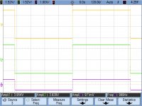
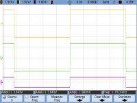
And the rest of the scope pics. The last pic is a zoom to view the slight ring at 20kHz. I forgot to mention that the load was 75ohms for the scope tests. It's probably obvious just looking at the scope pics, but Yellow is R, Green is L, and Purple is input. Input voltage was 1Vpp, and frequency is indicated on the bottom-right of the scope captures.
Attachments
-
 JDB HPA Scope test-20kHz, Zoom.jpg251.4 KB · Views: 52
 -
 JDB HPA Scope test-20kHz.jpg165.9 KB · Views: 51
 -
 JDB HPA Scope test-15kHz.jpg169.6 KB · Views: 45
 -
 JDB HPA Scope test-10kHz.jpg170.7 KB · Views: 43
 -
 JDB HPA Scope test-5kHz.jpg164.1 KB · Views: 43
 -
 JDB HPA Scope test-2kHz.jpg170.8 KB · Views: 48
Last edited:
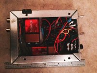
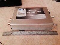
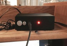
I also decided to share some pics of the amps in their enclosures. The full-size version is pretty much finished. The pocket version is an earlier prototype, utilizing alkaline 9Vs as I hadn't finished the charging circuit yet. The final version will probably look much nicer!
Attachments
Thanks for the update. I enjoyed reading that 🙂
You have done well getting samples too, that should certainly be interesting for extended listening tests. Sorry to hear about the hearing issues, one of the very real hazards of playing in an orchestra. If you find you want more "sparkle" from the amp then you can easily modify the response by bypassing the lower feedback resistor with a series coupled cap and resistor. That would be an easy way to get a rising treble response.
Excellent job, you've really got to grips with it all.
You might find this interesting (just for reference) that gives a modified response in the midband of the audio range.
http://www.diyaudio.com/forums/soli...mpaired-setup-new-television.html#post2419559
The amp I've been tinkering with as a student 3 years ago. My favorite schematic! I'm listening to it right now.
I've build it 3 times. My conclusion is that the simpler the design is, the better. In other words, remove everything that won't harm it's operation like caps and resistors in the circuit path. Remove output resistors.
Second, use really good filtering close to the opamp. Refer to AD797 datasheet.
I use 10nF+100nF+1uF(tantalum). Same goes for the buffers as well. I haven't tried anything better than the LM317/337 combo though.
Third, I achieved better results with 2 buffers per channel in parallel. Not only you get 500mA, it also lowers output resistance in half. At this point, the grounding is critical, you make a good one. I've achieved 0.026 Ohm output resistance with a perfboard design. It also alters channel separation.
Opamps. I've tried NE5532, OPA1612, OPA2134, AD8599, LM4962 ans some others. The LM4562/LME49720 is the best for me. Google Bob Pease's measurements on it.
And last, get a nice soundcard, and carry measurements with RMAA or similar. Much easier and useful.
Something important: A clean, accurate build should have no problems with oscillations with audio opamps like LM4562, OPA2134, NE5532 etc. So check that first. I've had similar problems and built the amp again instead.
Last edited:
Well, I can finally say I'm 100% done with the full size version, and only a few things need to be worked out on the portable version, namely battery charging and battery life. I may try to figure out how to implement some LiPo batteries. I have 6 digital camera sized ones that fit perfectly and are over triple the capacity of the 200mAh 8.4V "9 volts" (725mAh) and they're 3.7V nominal so I could ramp up voltage to +/-10v or +/-12v fully charged.
Anyhow, the only changes I've made were switching to AD797s instead of the OPA827s and LME49600s instead of BUF634s. It's not a huge change, but it sounds clearer and smoother to me. The 15pF caps are gone, no more oscillation after I enabled the bandwidth pin on the buffers. Oops.
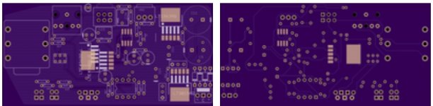
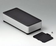
I also have ordered some PCBs to be made. I went with Vasquo's recommendation and chose OSH Park. I haven't seen them yet, but based on pricing, included options, and customer service, I feel I'll definitely be using them again. Sorry for the low res pics, they were all I could get after I ordered them. I should have saved the nicer pics I used to inspect the work they were going to do. Oh well. I also am due to receive a really cool extruded aluminum enclosure from OKW soon.....hopefully sooner than later! I've included a pic.
I'll post some pics of the boards populated when I can get that done. : ) Next week is Finals, and my last one is on Tuesday so hopefully I'll be able to complete them pretty quickly.
Anyhow, the only changes I've made were switching to AD797s instead of the OPA827s and LME49600s instead of BUF634s. It's not a huge change, but it sounds clearer and smoother to me. The 15pF caps are gone, no more oscillation after I enabled the bandwidth pin on the buffers. Oops.
I also have ordered some PCBs to be made. I went with Vasquo's recommendation and chose OSH Park. I haven't seen them yet, but based on pricing, included options, and customer service, I feel I'll definitely be using them again. Sorry for the low res pics, they were all I could get after I ordered them. I should have saved the nicer pics I used to inspect the work they were going to do. Oh well. I also am due to receive a really cool extruded aluminum enclosure from OKW soon.....hopefully sooner than later! I've included a pic.
I'll post some pics of the boards populated when I can get that done. : ) Next week is Finals, and my last one is on Tuesday so hopefully I'll be able to complete them pretty quickly.
Attachments
- Status
- Not open for further replies.
- Home
- Amplifiers
- Headphone Systems
- My first HPA design...comments please!