Hi all, I'm a long-time lurker and I've only posted a couple times. I'm currently in school to become an EE and in the time I've been in school, I've learned a lot compared to my earlier design efforts. So far I've built it up on protoboard and tests well on the scope and with my headphones. Anyway, about the amp:
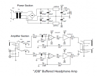
-The heart of the design is a Burr-Brown OPA2107 op-amp and two BUF634 buffers, each with 250mA output each. The buffers are kept inside the op-amp feedback loop to compensate for any error that either the buffers or the op-amp create.
-Power supply is +/- 12V, 2A max.
-Inputs are switchable between RCA or 3.5mm TRS
-Outputs are switchable between 3.5mm TRS or 6.35mm TRS. I've also considered adding RCAs to the output so it can function as a preamp.
-The name is derived from my initials. Please let me know what you think!
(Not that it really matters, but this isn't a school assignment, so say anything you want to about it.)
Attachments
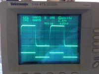
Some scope results for some proof it works. In order,
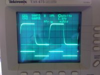
1: 100Hz square wave fed from function generator into input jack, output read at output jack, into 40Ω dummy load. CH1 is the output, and CH2 is monitoring input for comparison.
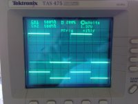
2: Same as above, 500Hz
3: 1kHz
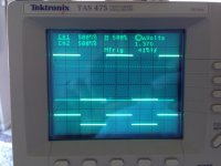
4: 10kHz
5: 20kHz
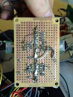
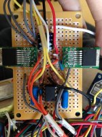
6 & 7: Picture of the actual amp. Note this is an older picture and it has LHM6321 buffers instead of BUF634s.
I think the breakdown of the waveform >10kHz is due to it being built on protoboard, once I get my PCB finalized then hopefully things will look a little better.
1: 100Hz square wave fed from function generator into input jack, output read at output jack, into 40Ω dummy load. CH1 is the output, and CH2 is monitoring input for comparison.
2: Same as above, 500Hz
3: 1kHz
4: 10kHz
5: 20kHz
6 & 7: Picture of the actual amp. Note this is an older picture and it has LHM6321 buffers instead of BUF634s.
I think the breakdown of the waveform >10kHz is due to it being built on protoboard, once I get my PCB finalized then hopefully things will look a little better.
Attachments

That's great Joe, and its always nice to see real scope shots and measurements to back things up.
Only comments I would make... and its not finding fault... is that the 100k volume pot is perhaps a little on the high side and may be responsible for the slight high frequency roll off visible at 20kHz. That's because a filter is formed with the resistance of the pot and any input/stray capacitance. R3 and R4 also have the effect of altering the law of the pot somewhat.
Only comments I would make... and its not finding fault... is that the 100k volume pot is perhaps a little on the high side and may be responsible for the slight high frequency roll off visible at 20kHz. That's because a filter is formed with the resistance of the pot and any input/stray capacitance. R3 and R4 also have the effect of altering the law of the pot somewhat.
Greetings from extremely hot and I'm-not-going-near-a-soldering-iron-until-September Kyoto.
Your circuit is a simple re-working of the example from the BUF34 datasheet, reproduced below. No shame in that, though it would have been nice had you made that clear. Simonov, who posts on this forum from time to time, has a write up on his blog, here. There are many others.
1. As Mooly notes, the volume pot should be 10-25k, not 100k, as 100k is your load resistor and you want about 1/5th of that ideally.
2. A headphone powered by 7812/7912 is going to sound like every other headphone amp on the planet powered by 7812/7912s, i.e. washed out and grainy.
3. While 2.2uF after the vregs is the databook value, most audio circuits use much higher capacitance, especially for a headphone amplifier circuit.
4. R7, R8, and R12, R13 don't accomplish anything useful as far as I can see.
The buffered op amp headphone amp is one of those circuits that on paper should be ideal, but in practice doesn't seem to satisfy people for very long. My opinion, entirely empirical, is that this is attributable to 1) the nasty voltage regulators most people insist on using and 2) putting the buffer into the feedback loop, which probably causes more problems for the op amp than it solves for the buffer.
Attachments

Thanks for the replies, Mooly and rjm!
I too wasn't completely sure about the 100K pot, but I eventually decided to use it because it's the only value of the Alps RK27 I can find. Perhaps I'll give a 10K RK097 a shot and see what happens. I agree it's probably the biggest problem I have right now with the amp.
That's interesting about the datasheet application for the BUF634. I don't know if I made it clear earlier but I first tried an LMH6321, then LME49600, and finally tried the BUF634. I don't know if it means I'm on the right track or if it looks like I'm a copy-cat! Thanks for the link to Simonov's page, I'm sure it'll be helpful.
What would you use in place of 7812/7912? As far as I can tell, they regulate voltage pretty well and supply plenty of current for what I do. I'm willing to try anything new as long as it doesn't cost me too much, what would you use? I also found that 2.2uF is plenty, but upon your recommendation, I'll try something a little higher. I did try 10uF tantalum but didn't change anything. Do you recommend sticking with film caps or electrolytics?
R7 & 8 probably aren't necessary but I put them there for a little protection to the buffers from the op-amp. R12 & 13 were added late in the process to help the circuit from reacting too much to headphones, and while it doesn't sound any different, it was visible on the scope that it did help a little. Again, probably not 100% necessary, I agree.
I'll try leaving the buffers out of the feedback loop to see what happens.
Thanks for the comments!
I tend to look at regulators this way (and everyone has their own ideas) in that the biggest problems is actually knowing and understanding what you are trying to accomplish. By that I mean identifying what problems you are looking to correct... if that makes sense 🙂
If your rails are clean as looked at on a scope and aren't modulated at all by the amp driving the headphone then your already at a good point. The problem with any regulator is deploying it correctly and what can happen is that you find the output at the reg itself is super clean, but add few cm of wire to its destination and its not quite as good. So to get that last few percent of performance you need to be looking at absolutely correct grounding techniques and super short wiring, perhaps with the regulators physically next to the parts they are supplying. And doing all that is much easier said than done.
I can't just tell from your pictures whether you have any local decoupling around the IC's. That's important when the regs are some way off.
Actually the output impedance of a 100k pot (on a low-impedance source) is 50k||50k = 25k max. (I'll blame it on the heat. 😉)1. As Mooly notes, the volume pot should be 10-25k, not 100k, as 100k is your load resistor and you want about 1/5th of that ideally.
I'd be more worried about impedance imbalance. This part uses a cascoded FET input stage and as such should perform better than the average JFET input device in Samuel Groner's epic bunch of measurements when it comes to input impedance distortion, but a maximum difference of about 22k still is kinda high.
Reviews of this part mention some common-mode distortion, so a high-end design may attempt a common-mode bootstrap on the OPA... oh wait, it's a dual. I mean, one could still do it, as (L+R) generally >> (L-R), but I'd have my doubts about effectiveness and stability with even moderate channel imbalance...
I'd check stability the hard way - hang a 10 nF on the output, and if that passes, a 47 nF. The capacitance of a headphone cable alone may be in the 1 nF vicinity. It's not like I'd expect anything major with the relatively slow OPA2107 at a gain of 4 - the 1 ohms may already be far more than sufficient to ensure stability, and if lower Zout were desired, I'd give a Zobel network a shot.
A minimal reduction in noise would still be possible by cutting down on feedback network resistor values, only about 2 dB though. May not be worth the increase in Pdiss. Use metal films. JFTR, these go to input ground, a Zobel would go to power ground.
Actually 78xx/79xx regs tend to be quite adequate for high-PSRR, moderately-low-noise circuits like this (we have >= 40 dB of spare open-loop gain over most of the audio BW here after all). Next time I'd rather be using an On Semi part with 12 dB lower specified noise though (as far as 7912s go). Or if you want to get fancy, the classic LM317/337 setup with caps on the adjust pin. As mentioned, proper grounding is absolutely essential if you actually want to obtain the kind of PSRR quoted in the datasheet, as well as attention to some other snags like stability with low-ESR loading.
Last edited:
@sgrossklass yeah I know, it just bugs me when I see it: not only does the net input impedance now vary between 100k and 50k, but the log. tracking of the pot is thrown off by, what, up to 6 dB?
I wouldn't get too upset about the mismatch seen on the op amp inputs though. That's an un-winable war .. its always going to vary a little bit depending on the position of the volume control, and at the typical listening position its reasonably close.
Your careful wording forces me to agree. 🙂 And you are right. Indeed its a bit of a pain to convince someone that they are best replaced with something better since from a datasheet perspective they are indeed perfectly sufficient.
Measurements are difficult and rarely unequivocal, while appeals to the hypothetical - "it is possible that such and such might have a negative impact" are always open ended. So either one looks at what other people have found re. e.g. LM317 vs LM7812 vs ?, or one simply builds and listens to a few different options to decide for themselves.
Let me put it this way, I've never read of anyone replacing the LM7812 with something else and not being able to tell the difference, which refutes at the very least the "sufficient and therefore no impact on the sound" argument.
Personally I favor the zener-diode regulated pass transistor, though others vouch for an unregulated supply at least for the output stage. LM7912, as a I noted earlier, is grainy, while the LM317 tends rather to be too clinical. Of course what kind of capacitance, how much and where you distribute it around the layout makes a big difference too.
It's still a trial and error business, to my mind.
I wouldn't get too upset about the mismatch seen on the op amp inputs though. That's an un-winable war .. its always going to vary a little bit depending on the position of the volume control, and at the typical listening position its reasonably close.
Actually 78xx/79xx regs tend to be quite adequate for high-PSRR, moderately-low-noise circuits like this
Your careful wording forces me to agree. 🙂 And you are right. Indeed its a bit of a pain to convince someone that they are best replaced with something better since from a datasheet perspective they are indeed perfectly sufficient.
Measurements are difficult and rarely unequivocal, while appeals to the hypothetical - "it is possible that such and such might have a negative impact" are always open ended. So either one looks at what other people have found re. e.g. LM317 vs LM7812 vs ?, or one simply builds and listens to a few different options to decide for themselves.
Let me put it this way, I've never read of anyone replacing the LM7812 with something else and not being able to tell the difference, which refutes at the very least the "sufficient and therefore no impact on the sound" argument.
Personally I favor the zener-diode regulated pass transistor, though others vouch for an unregulated supply at least for the output stage. LM7912, as a I noted earlier, is grainy, while the LM317 tends rather to be too clinical. Of course what kind of capacitance, how much and where you distribute it around the layout makes a big difference too.
It's still a trial and error business, to my mind.
As for the regulators, I found LM2940-12 vs. 7812 and LM2990-12 vs. 7912 far more superior and pin compatible.
But what if if it were just used to drive a bunch of LEDs? 😛Let me put it this way, I've never read of anyone replacing the LM7812 with something else and not being able to tell the difference, which refutes at the very least the "sufficient and therefore no impact on the sound" argument.
More seriously, people who just upgraded their regulators would seem highly prone to fooling themselves. It is sighted listening with no second, unmodified sample of the same equipment at hand for a direct comparison. They just put a fair bit of effort in, so there better be an improvement. It's like those people who just bought a fancy $300-or-so audio cable. (I'd rather connect the output of $equipment to a low-noise preamp and feed that into a soundcard line-in or somesuch, for a little comparison of noise level before/after.)
That being said, 300 µV of noise (TI part, 200 µV for Fairchild), 10 Hz - 100 kHz for the LM7912 is quite the lot (and zeners being zeners, I would assume a fair chunk of this would be at lower frequencies). A typical ripple rejection of 60 dB @120 Hz is hardly astronomical either. (The corresponding 78xx parts perform a fair bit better in both respects.) With many opamps having their VAS on the negative rail and essentially -PSRR being = spare OLG, you can see why this may turn out to be a problem. Potentially even more so if there is capacitive load peaking, so better not be too stingy with output-side electrolytics. You'll probably all be aware of the fun to be had with noise in 3-terminal regs.
But like I said, a low-gain opamp circuit using a moderately-low-noise part of decent GBW should normally be sufficient to keep this at bay over the audio BW. If you don't feel so comfortable about that, use a lower-noise negative reg like the ON Semi MC7912 - 75 µV typ. (Their 78xx doesn't seem to be so hot, as it seems it's got 120 µV of noise, whereas it seems Fairchild forgot to change units when they changed to µV/Vo to µV in the non-A parts. Looks like those are equivalent to what others call 78Mxx, which generally have better noise specs. But do beware, TI's negative LM79M12 is a noisy bugger - 400 µV!) I'd say if you get both positive and negative parts in the 75 µV vicinity, you should be good for a lot of audio applications. There still is the option of using some RC filtering on sensitive circuit parts.
As you can see, there's a fair bit of variation in noise performance alone when it comes to supposedly generic three-terminal regs. And that's just the specs, which unfortunately may not always match real-life performance in such "jellybean" parts (case in point: some NE5532s which seem to have IIB of more like 1 µA rather than the specified "typical" 200 nA). In a cost-sensitive design, a close look at your "generic" regulators may well pay for itself.
If I were designing a super-low-noise circuit around AD797s or something, I probably wouldn't be using 78xx/79xx regs. Not "barefoot", anyway - maybe with a cap multiplier. Otherwise there's the trusty LM317/337 combo with adjust pin caps, or a host of better-performing (if more expensive) newer regs.
If you have been listening to an audio device for years, then replace the regulators and your wife cries from the neigbor room "what you have done, it sounds so much better" (personal experience) then you are not likely to deceive yourself. And it is not the noise performance that makes sonic difference between regulators.More seriously, people who just upgraded their regulators would seem highly prone to fooling themselves.
...
As you can see, there's a fair bit of variation in noise performance alone when it comes to supposedly generic three-terminal regs.
...
If I were designing a super-low-noise circuit around AD797s or something, I probably wouldn't be using 78xx/79xx regs.
I tend to take such tales with approximately half a salt mine, but this would seem to suggest that the circuit at hand cares a lot more about dynamic supply impedance than I'd personally like (i.e. low PSRR). Some basic before/after measurements should show what's going on.
There are two basic design approaches when it comes to this:
Either use a low-complexity circuit with low PSRR (but otherwise good performance) plus fancy / complex voltage regulation,
or use a complex circuit with high PSRR that's not too picky about its supplies.
In many applications you have no choice but to go the latter route for economic or other concerns (with ICs, complexity has become quite cheap), but in DIY we have the luxury of being able to go with the first as well.
In practice both extremes have their drawbacks - for example, easily-achievable PSRR tends to be limited at higher frequencies, while low-PSRR circuits may still have other undesirable surprises to offer. A good design is invariably going to involve a compromise of some kind between the two. I'd be leaning more towards the "high PSRR" camp, which tends to have some other advantages as well. But generally speaking, there is no One True Way of achieving best performance, the designer has a certain degree of freedom here (and thankfully, I may add, where'd be the fun otherwise?).
You should merely be aware of the problem area at all, and not be surprised when powering a 1-transistor MC prepre or 4-transistor Class A (or even AB) headphone amp from a basic 78xx/79xx combo does not exactly yield ideal results ("...but it simulated so well...!"). The supply is always part of your circuit, like it or not.
Unfortunate combinations do occur in practice - for example, the original Leach preamp design had almost no -PSRR and only basic R-Zener voltage regulation (which isn't exactly super-quiet, I imagine).
Last edited:
Either use a low-complexity circuit with low PSRR (but otherwise good performance) plus fancy / complex voltage regulation, or use a complex circuit with high PSRR that's not too picky about its supplies.
Maybe I should leave it to Captain Obvious to take this one? Besides its not even true: There is very little cost to using a "fancy" voltage regulation in low current audio circuits, so if you think it sounds better there is no reason not to.
Look if you want to be stubbornly skeptical in the face of anecdotal evidence, fine. Personally I find such information extremely valuable, especially put together with my own experience. And my reading of that is as follows: it doesn't matter what the PSRR numbers on the datasheet are, you always hear the power supply, all of it: transformer, diodes, capacitors, regulators, and layout. Many changes are surprisingly consistent, though others, like layout or bypassing, are almost impossible to pin down with any certainty.
Thanks for the discussion guys, it seems like power supplies for audio can be much more complex than I initially believed. Just to see how my design fared, I did some careful exploration with the original power supply I designed. Messing around with the trigger on my scope I was able to detect some stuff I hadn't seen before, and here are the results. This is with no load, just idle, I'll have to do the more detailed results later. (I'm taking summer classes this semester and finals are next week.) Note these were taken at the max settings on my scope (Tek TAS475), 20mV/div and 20nS/div. Ch 1 is the 7812, and the 7912 is Ch 2.


Last edited:
Before you go any further, set the scope and amp up so that you get the same hf hash showing as above.
Now remove the scope probes from the amp and connect probe tip to probe ground. You should get a straight trace with no noise. Still keeping the probe shorted touch the tip onto the ground point of the amp you were using before.
Does the trace stay clean or do you see the noise return ?
Now remove the scope probes from the amp and connect probe tip to probe ground. You should get a straight trace with no noise. Still keeping the probe shorted touch the tip onto the ground point of the amp you were using before.
Does the trace stay clean or do you see the noise return ?
Hi Mooly,
First of all, thanks so much for your sincere interest and will to help me, it's rare to find someone like that in real life, and even more rare on the internet. When I initially saw that waveform I was a little surprised, so I thought it had to be an error. I switched scope probes, tried my older backup scope (Tek 2225), tried switching to different wall sockets, and no change. I even brought it to school to use one of our newer full-digital 500Mhz scopes in the EE lab and I got the same results. I didn't try shorting the tip and ground lead though, that'll be the next step I'll try. Right now though I'm guessing it's due to either being constructed on protoboard which leads to a crummy layout, or the fact that they're old and have been soldered and re-soldered four or five times due to them being used in different circuits. Right now I'm designing one based upon LM317/337 as previous posters have mentioned rather than 7812/7912, so maybe that'll be the solution that works out best right now.
First of all, thanks so much for your sincere interest and will to help me, it's rare to find someone like that in real life, and even more rare on the internet. When I initially saw that waveform I was a little surprised, so I thought it had to be an error. I switched scope probes, tried my older backup scope (Tek 2225), tried switching to different wall sockets, and no change. I even brought it to school to use one of our newer full-digital 500Mhz scopes in the EE lab and I got the same results. I didn't try shorting the tip and ground lead though, that'll be the next step I'll try. Right now though I'm guessing it's due to either being constructed on protoboard which leads to a crummy layout, or the fact that they're old and have been soldered and re-soldered four or five times due to them being used in different circuits. Right now I'm designing one based upon LM317/337 as previous posters have mentioned rather than 7812/7912, so maybe that'll be the solution that works out best right now.
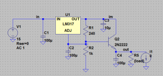
I suggest having a separate supply for the opamps (use TL431 shunt regs) and keep the LM317/337s (well slugged with a suitably large cap for low noise) for the buffers. This will largely prevent the buffer's switching noise affecting the opamp via the supply rails.
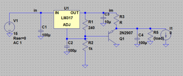
It is possible to use LM317/337 reference voltage and an additional BJT to do an extra filtering. Just put a sufficient value capacitor into reference node and it will give you much lower noise than TL431. If you need a lower output impedance, CFP can be used instead of a single BJT.
Disadvantage of this method is in some voltage vs temperature dependance, which usually not a big deal with opamps.
Disadvantage of this method is in some voltage vs temperature dependance, which usually not a big deal with opamps.
Attachments
Last edited:
Hi Mooly,
First of all, thanks so much for your sincere interest and will to help me, it's rare to find someone like that in real life, and even more rare on the internet. When I initially saw that waveform I was a little surprised, so I thought it had to be an error. I switched scope probes, tried my older backup scope (Tek 2225), tried switching to different wall sockets, and no change. I even brought it to school to use one of our newer full-digital 500Mhz scopes in the EE lab and I got the same results. I didn't try shorting the tip and ground lead though, that'll be the next step I'll try. Right now though I'm guessing it's due to either being constructed on protoboard which leads to a crummy layout, or the fact that they're old and have been soldered and re-soldered four or five times due to them being used in different circuits. Right now I'm designing one based upon LM317/337 as previous posters have mentioned rather than 7812/7912, so maybe that'll be the solution that works out best right now.
Thanks for the kind words... and its nice to see actual real scope shots to back up circuit designs and builds rather than just taking things on trust from simulations and so on.
So you've tried it all in a different location and with different test gear and its the same. That's sort of rules out what I was thinking earlier (try it non the less for interest though).
Have you any "local" decoupling around both IC's ? Its well worth trying a small cap (say 0.1 to .47 film or ceramic, perhaps in series with a 1 ohm carbon or metal film resistor mounted directly across the power supply pins of each IC.
VHF oscillation, hmm. That can't be the main feedback loop (it's far slower than that), so I guess we are looking at local oscillation around the buffer. Layout gets quite critical at frequencies like that. Do experiment with rail decoupling as suggested. (On a hunch, I would also try a small cap to ground at the buffer input.)
If that doesn't help, rail or ground inductances may be too high. Remember - the larger the loop area and the thinner the conductor, the higher the inductance. Hence why they use ground planes in RF. (You just don't want one under the inverting input of your opamp.) Speaking of which, maybe you can pick up some tricks for hand-building circuits suitable for RF from the ham radio crowd.
If that doesn't help, rail or ground inductances may be too high. Remember - the larger the loop area and the thinner the conductor, the higher the inductance. Hence why they use ground planes in RF. (You just don't want one under the inverting input of your opamp.) Speaking of which, maybe you can pick up some tricks for hand-building circuits suitable for RF from the ham radio crowd.
- Status
- Not open for further replies.
- Home
- Amplifiers
- Headphone Systems
- My first HPA design...comments please!