Built a phono stage today, based on this circuit: http://sound.westhost.com/p06-f1.gif
Built it as dual mono, each channel on it's own piece of protoboard 😀
Used NE5532P op-amps, Panasonic FM electrolytics and K73-16V on output.
Mostly 5% resistors, because electronics store was out of metal film 🙁
I have a few questions that I'd like to ask first before I case it up.
I am currently using a ceramic cap (a green one, if that says anything) as C1 in feedback. Would a film capacitor in feedback loop give better results?
Also, I currently have two 1000uf caps for filtering right on the board. Should I replace them with smaller, say, 22uf caps and put the 1000's on the power supply board? I've heard that smaller (faster?) electros should be used right on the board.
Also, does it matter whether is put rail decoupling caps on the board, or straight on op-amp's power pins?
Any tips on op-amp based phono stages?
I have a FET/transistor combo phono that I salvaged from an old pre-amp, can't wait to get both up and running and compare.
I'll post pics of my ghetto looking board tomorrow 🙂
Happy holidays!
Okay so I assembled this thing onto an aluminium plate for now, with a +-12V regulated power supply. I'm using this with a brand new AT95E so both the phono and the cartridge still need burn-in time.
Right now, it sounds quite alright. However, I am having a problem with subsonics. How would I go about adding a passive subsonic filter?
Also, will the ceramic cap in feedback have a negative impact on sound or no?
Right now, it sounds quite alright. However, I am having a problem with subsonics. How would I go about adding a passive subsonic filter?
Also, will the ceramic cap in feedback have a negative impact on sound or no?
I am having a problem with subsonics. How would I go about adding a passive subsonic filter?
Also, will the ceramic cap in feedback have a negative impact on sound or no?
Your subsonic problem may be acoustic feedback. There is already a high pass filter at the output, just make the 1uF capacitor smaller.
The NFB ceramic capacitor is unlikely to be good for that purpose, only a COG/NPO type ceramic is adequate there.
Last edited:
I agree with Rayma. Neither C1 nor C4 should be ceramic. It is very unlikely that such high value ceramic capacitors are class-I devices, and class-II and class-III capacitors distort, absorb dielectrically and are quite inaccurate.
Decoupling capacitors in an analogue circuit should be close enough to the active devices to prevent high-frequency instability due to supply wiring inductance. If you place them right next to the op-amps on the board or straight on the power pins, that should be OK.
Decoupling capacitors in an analogue circuit should be close enough to the active devices to prevent high-frequency instability due to supply wiring inductance. If you place them right next to the op-amps on the board or straight on the power pins, that should be OK.
Last edited:
The 1uF output cap? Okay, well I actually have a 4.7uF in there 😱Your subsonic problem may be acoustic feedback. There is already a high pass filter at the output, just make the 1uF capacitor smaller.
The NFB ceramic capacitor is unlikely to be good for that purpose, only a COG/NPO type ceramic is adequate there.
What should I use? Would 470nF be good?
The subsonics I am experiencing are not random, they go along with small warps in the record.
I think I have some mains rated Y caps, would those be good for feedback? Or should I go with film instead?
Thanks! 🙂
Go for film capacitors, preferably polystyrene or polypropylene, but PPS or MKT is also much better than class-II ceramic.
The 1uF output cap? Okay, well I actually have a 4.7uF in there 😱
What should I use? Would 470nF be good?
I think I have some mains rated Y caps, would those be good for feedback? Or should I go with film instead?
Thanks! 🙂
For a 10Hz roll off, use a 0.33uF capacitor. This assumes the input impedance of the amplifier is 100k.
If not use the formula: 1/(2 x 3.14 x Cout x (100k paralleled with Rin amplifier))
Definitely use a good film capacitor for the RIAA.
Last edited:
I have some soviet caps in stock. Some different K73 PTFE and also MBM and BM-2, etc... I'll look into it, see what I have and post here.Can you get any of the Soviet-era Teflon capacitors? They are physically huge, but wonderful.
I need to measure my amp's input first, then we'll see what I can use 🙂
Another thing that I've been wondering is that can you place a decoupling cap, say a 100nF film or disc, between the + and - rail? I think I've seen it somewhere, and thought maybe I'll throw in some 😀
I've just spent about an hour listening to this pre, and even with the ceramic caps and big output caps, I really do like the sound 🙂
As for decoupling cap placement, I have two 100nF film capacitors per rail, about two centimeters away from the op-amp, if I place them closer, how will that change SQ?
Last edited:
For an NE5532, two centimetres should be close enough not to cause instability, so placing them even closer will not have any impact.
Okay, I put some film caps in place of the feedback ceramics. Can't say it's a huge improvement, but a little bit I guess.
So how about that decoupling cap between the rails, should I? 😀
So how about that decoupling cap between the rails, should I? 😀
The 1uF output cap? Okay, well I actually have a 4.7uF in there 😱
...
A straight forward reason for your platter rumble.
It's not documented very well, but the output cap is the high pass filter for Rod's 06 RIAA.
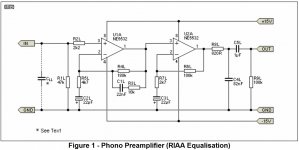
So when you quadrupled the value (1u --> 4.7u), it allowed much more low frequency platter rumble through (~5Hz).
Also not well documented, Rod's06 assumes the standard 10k to set the high pass filter:
f=1/(2*pi*R*C)=1/(2*pi*10k*1u)=16Hz
What is the load of your next stage? If it's high (50k, 100k), that will also lower the low freq cut off.
Watch what happens if you have both a big cap (4.7u) and a high load (100k) Double-whammy!
f=1/(2*pi*R*C)=1/(2*pi*100k*4.7u)=0.34Hz 😱
That'll let an ... earthquake through!
You're interest made my dig mine out!
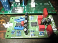
😉
Ah yes, I used my sweet OPA2132P for this!
It's a unique design (feedback, filters) but what's not shown in the schematic is the interesting ps bypassing: there are no high freq caps from V+ to GND or V- to GND but from V+ to V-.
Cheers,
Jeff
Last edited:
Thank you for the reply, Jeff!A straight forward reason for your platter rumble.
It's not documented very well, but the output cap is the high pass filter for Rod's 06 RIAA.
View attachment 455533
So when you quadrupled the value (1 --> 4.7), it allowed much more low frequency platter rumble through.
Also not well documented, Rod's06 assumes the standard 10k to set the high pass filter:
f=1/(2*pi*R*C)=1/(2*pi*10k*1u)=16Hz
What is the load of your next stage? If it's high (50k, 100k), that will also lower the low freq cut off.
You're interest made my dig mine out!
View attachment 455532
😉
It's a unique design (feedback, filters) but what's not shown in the schematic is the interesting ps bypassing: there are no high freq caps from V+ to GND or V- to GND but from V+ to V-.
Cheers,
Jeff
I have to compliment your work, it looks very well done! 🙂
Here is what mine currently looks like:
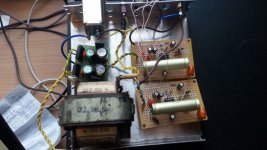
Photo quality is a bit crap, but whatever.
I measured my amplifier's input impedance from in+ to ground and it's 44.1K per channel.
Yes, there are no filter or bypass caps shown on the schematic, but Elliot's website recommend 0.1uF + 10uF. I used 0.1uF + 22uF low ESR from each rail to ground.
So should I drop in another 0.1uF between + and - rails?
I checked my Soviet cap supply and I currently have no 22nF in stock 🙁
Thank you for the reply, Jeff!
I have to compliment your work, it looks very well done! 🙂
...
That's just Rod's nice PCB
...I measured my amplifier's input impedance from in+ to ground and it's 44.1K per channel...
I assume you meant preamp input impedance (unless you are plugging your phono RIAA straight into your poweramp! Wow!) 😉
So you had C=4.7u and R=44k
f=1/(2*pi*R*C)=1/(2*pi*44k*4.7u)=0.77Hz
"Let's get ready to Rrrrrr Ummmmmmmmmm blllllllllllle!"

😉
... I used 0.1uF + 22uF low ESR from each rail to ground.
So should I drop in another 0.1uF between + and - rails?
...
I'd keep what you have now (it's the standard) and then try Rod's (V+ to V-) later.
So, fix your output filter.
Rework the formula to isolate C, use Rod's original f=16Hz and your preamp R=44k
C=1/(2*pi*R*f)=1/(2*pi*44k*16)=0.22uF
You want a 0.22uF output cap.
Then see if you still have rumble and we'll go from there. 🙂
If you do need a more steep/advanced rumble filter there's Rod's
http://sound.westhost.com/project99.htm
and a very cool one
http://www.diyaudio.com/forums/anal...ore-effective-than-just-high-pass-filter.html
from Monty78pig
Cheers and Happy Holidays (if you're into them)
Jeff
PS
...I checked my Soviet cap supply and I currently have no 22nF in stock🙁
If you're into exotic caps you'd love the BoozeHound:
JFET Phono/RIAA Preamplifier kit – Boozhound Laboratories
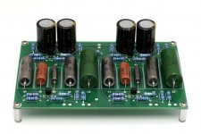
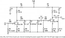
It's also sort of the opposite design philosophy ... most basic circ possible (single JFET) with passive RIAA and exotic caps vs Rod's more advanced/unique circ (opamps) with active RIAA and standard parts
Would be fun to compare ...
Last edited:
Thank you for the reply, Jeff!
I have to compliment your work, it looks very well done! 🙂
...
And don't look too close, I have to do my own filter recalculations! 😱
One of the cool things about Rod's design is how he has the RIAA rolloff at the output of the circuit:
R8 and C4
f=1/(2*pi*R*C)=1/(2*pi*820*82n)=2.4k
The only Panasonic P polypro film I had was 100n
f=1/(2*pi*R*C)=1/(2*pi*820*100n)=1.9k 😱 (and this is way more important than the rumble filter since it's a main part of the RIAA curve! Doh! )
So, I need to find a 82n (I don't think I have one) or recalc for a new R8 value (isolate R) to go with my 100n (standard value)
R=1/(2*pi*C*f)=1/(2*pi*100n*2.4k)=660 ohm
Hmm, that might be too low for the opamp to drive ... let me look again for an 82n or even smaller so I can increase the R ...
Okay I guess I measured the wrong thing? 😀 Because I measured the input of my actual power amplifier. Well, it's actually an integrated amplifier. I'm running this thing into the AUX input and it works fine?! 😀
I have seen the BoozeHound before, but it was a bit too expensive for me 😀 But I might try that next. I'm not like a huge fan of exotic caps, but since I live in Estonia, Soviet caps are very common and cheap here.
What do I have to measure, the output resistance of the phono or what?
Sorry, I'm a bit of a noob.
I also have another phono stage to try out. From a Soviet pre-amplifier. Built with Soviet parts, of course 😀 I just changed the electrolytics.
Maybe you could give me some opinions or tips on this thing as well? 🙂
Power supply for this circuit was somewhere between 25-30V, IIRC. Dual polarity, of course.
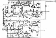

Oh, I see you meant integrated amp.
Ok, R9, R10 are 46.4k but I believe that's the amp section.
Do you have the input and volume part of the integrated amp schematic?
Can you measure it? DMM measuring R and connect to aux, cd, etc (whatever input you're using)
Most Integrated amp's just switch the inputs and then connect it to a 10, 20 or 47k pot.
Others put a buffer before the pot with 100 - 250k input.
---------------------------------------------------------------------------------------
Nevertheless, using 1uF for the output cap will at least put you 'in the ball-park'!
Cheers my friend, we'll get you going!
Jeff
PS To me, real Russia caps are exotic!
Last edited:
I just realized how retarded my measuring was 😀Oh, I see you meant integrated amp.
Ok, R9, R10 are 46.4k but I believe that's the amp section.
Do you have the input and volume part of the integrated amp schematic?
Can you measure it? DMM measuring R and connect to aux, cd, etc (whatever input you're using)
Most Integrated amp's just switch the inputs and then connect it to a 10, 20 or 47k pot.
Others put a buffer before the pot with 100 - 250k input.
---------------------------------------------------------------------------------------
Nevertheless, using 1uF for the output cap will at least put you 'in the ball-park'!
Cheers my friend, we'll get you going!
Jeff
PS To me, real Russia caps are exotic!
My amplifier has two line level inputs, which go into a rotary selector, then a 50k pot as a volume control, then a 3.9k resistor and then a 470n input cap.
But I really don't see how this matters, because when this phono stage is connected to the line level input, it plays just fine, and at the same level as my laptop (laptop at max volume, laptop has a pretty weak pre-amp) with the volume knob in the same position.
Anyways, I changed the output cap for a 470n K73-17 (couldn't find a 220 right now) and it doesn't seem to do much? 😀 And this is going to sound a bit audiophoolish, but should I bypass output caps with a small value K40P-2A PIO cap? I have some 0.047uF.
I'm sorry I'm a total noob with this.
As for the schematic I posted, what do you think? Should I even bother trying it? It is the actual phono stage. In the amplifier I pulled it from, this thing's output would have fed straight into the same line level inputs as, say, a tuner. Basically it was just between the input selector's phono input and the actual pre-amp.
I think it looks quite... alright? N-FETs on the input and everything 😀 46.4k load on the input should mach well with my AT95E.
Last edited:
I've also noticed that there is this weird noise in the output sometimes that sounds almost like wind in a microphone. Can't really notice it with music playing but with the tonearm up, it's pretty apparent.I just realized how retarded my measuring was 😀
My amplifier has two line level inputs, which go into a rotary selector, then a 50k pot as a volume control, then a 3.9k resistor and then a 470n input cap.
But I really don't see how this matters, because when this phono stage is connected to the line level input, it plays just fine, and at the same level as my laptop (laptop at max volume, laptop has a pretty weak pre-amp) with the volume knob in the same position.
Anyways, I changed the output cap for a 470n K73-17 (couldn't find a 220 right now) and it doesn't seem to do much? 😀 And this is going to sound a bit audiophoolish, but should I bypass output caps with a small value K40P-2A PIO cap? I have some 0.047uF.
I'm sorry I'm a total noob with this.
As for the schematic I posted, what do you think? Should I even bother trying it? It is the actual phono stage. In the amplifier I pulled it from, this thing's output would have fed straight into the same line level inputs as, say, a tuner. Basically it was just between the input selector's phono input and the actual pre-amp.
I think it looks quite... alright? N-FETs on the input and everything 😀 46.4k load on the input should mach well with my AT95E.
I've just spent hours listening to it, currently spinning some Modern Talking, with my AKG K14HDs through the big amplifier and I really like the sound.
- Status
- Not open for further replies.
- Home
- Amplifiers
- Chip Amps
- My first DIY phono stage - need advice!