Notes on output stage bias current
Bias was set at 100mA . Sink Temp : 38 deg C after 10 mins
Output stage current after 30 mins : 114 mA . Sink temp : 40 deg c
after 45 mins : 117 mA . 45 deg C
after 60 minutes : 153 mA 53 deg C
( music played at occasional clipping level after 45 minute period . So this measurement was after about 10 to 15 minutes after the music started playing.The heat sink was too hot to touch continuously.)
Member
Joined 2009
Paid Member
My advice in the past (on this thread I think) about this topology, which has ill defined bias current, is to use Hagerman Vbe multiplier. This is what I did on TGM5. I also had some VAS degeneration to reduce temperature stability. Together these worked fine.
Now that you have a CCS on the IPS you have another option. Put Q5 and Q6 on the heatsink. This is what I did in my TGM7 amplifier and it works fine for keeping good bias stability although.
Now that you have a CCS on the IPS you have another option. Put Q5 and Q6 on the heatsink. This is what I did in my TGM7 amplifier and it works fine for keeping good bias stability although.
No bias operation.
This is really bothering me. Acca's suggestion that the output stage biased slightly under conduction ( 3 diodes on a Darlington) sounds fine appears to be correct. Even the HF and low level signals don't seem to be mangled.
I am not sitting in front of the speakers all the time but the amp has been running for hours and I don't seem to be missing anything compared to a 100mA biased condition. If there is a difference it must be very small and subtle (?).
Hope others will try this out themselves and report back on what they find.
If this is real and I'm not missing out on something then it's a HUGE advantage to us.
I find even very busy tracks sound just the same as before. Low level music sounds the same including all the fine HF details . No edginess or roughness anywhere so far.
I need to check the FFT's . Pity I have no time to do that now.
Maybe do a diff test using Bill's software ( Diff test from Liberty Software). I can't do that any time soon. If there is someone who can it will be great.
I've been thinking about this a lot. Distortion goes up significantly as the output bias goes down. But maybe when playing at lower levels the ear can tolerate more distortion without it being obvious than at medium volume?
As for the HF sounding clean, it rides on top of the low frequency signals and bypasses the crossover point. Possible ?
With three diodes the output stage is not exactly completely cut off. I still detected about 5mA when it was cold.
But it's baffling that the very low bias state could not be very obviously audible. That FFT plot is really required !
5mA is still quite enough to reduce crossover distorsion to levels
in the 0.1-0.3% at mid power , that is at the threshold of audibility ,
but at very low power it s more intrusive since its amplitude stay
quasi constant with lower output levels , its audibility at low power
become obvious under 1mA or so.
in the 0.1-0.3% at mid power , that is at the threshold of audibility ,
but at very low power it s more intrusive since its amplitude stay
quasi constant with lower output levels , its audibility at low power
become obvious under 1mA or so.
Thanks Wahab. At quite low listening levels everything did sound fine. This is too low for normal musical enjoyment. I'll try very low levels and add a headphone in parallel with the speaker leads and see what happens. I want to see at what point the crossover distortion becomes intrusive and how badly mangled the HF can sound.
Quite an interesting situation ! 😉
Quite an interesting situation ! 😉
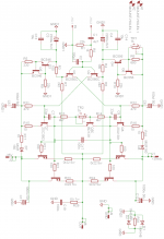
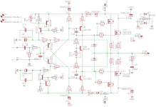
Today just finished the layout for the 2 pair power darlington but we can use the same layout for Toshiba 2SK1529/30 & 2SJ200/201 mosfet.
Between the two has only minimal difference so the same layout good for both!!!😀
The mosfet has 2X15 diode no 100nF cap the darlington has the 100nF cap and no diodes.
You can use TIP142/147 or BDW83C/84C if you can find the second one.
I want to test some Sanken darlington in these circuit, those parts was mentioned by me a couple page back.
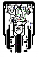
The size of the layout 80X127mm.
The PS rating with darlington 40-45V with the 2 pairs , with the Toshiba you can go up to 50-55V.
Adequate heatsinking must, please do not under estimate the size of the heatsink.
These was the last layout for these topology for now, I think is time to build the amp...
The layout was drawn by hand so I do not have silk screen, I use color codded lines for the parts
These is a simple amplifier with few parts so finding out parts location must be not a problem..
Green = resistors
Blue = capacitors
Red = Semiconductors
Grey = Jumpers
Purple = Diodes
Any question you have please ask.😀
Greetings Gabor
Between the two has only minimal difference so the same layout good for both!!!😀
The mosfet has 2X15 diode no 100nF cap the darlington has the 100nF cap and no diodes.
You can use TIP142/147 or BDW83C/84C if you can find the second one.
I want to test some Sanken darlington in these circuit, those parts was mentioned by me a couple page back.
The size of the layout 80X127mm.
The PS rating with darlington 40-45V with the 2 pairs , with the Toshiba you can go up to 50-55V.
Adequate heatsinking must, please do not under estimate the size of the heatsink.
These was the last layout for these topology for now, I think is time to build the amp...
The layout was drawn by hand so I do not have silk screen, I use color codded lines for the parts
These is a simple amplifier with few parts so finding out parts location must be not a problem..
Green = resistors
Blue = capacitors
Red = Semiconductors
Grey = Jumpers
Purple = Diodes
Any question you have please ask.😀
Greetings Gabor
Attachments
Low bias comparison.
Follow up on, no bias sound.
Finally I got time to check out the sound with no bias ( 5 mA !) again.
I played some complex sounds with 5mA bias and later with 35mA bias. Same signal level.
Playing music in the background without actually 'listening' to the music critically , both seem fine.
However if you sit in your 'listening position' and listen carefully, the low bias sound is noticeably 'noisy' on complex sounds. Simple sounds are harder to differentiate but any complex sound suffers most.Looks like IMD particularly has gone up a lot. Must be lots of things go wrong but maybe not as drastically as a measurement might indicate.
However I'd say that 5mA bias is to be avoided for 'serious' listening ! I don't know where the threshold is , where the difference with higher bias starts becoming noticeable. I don't have the time to check that out. It might just be 15 mA and higher I guess?
Will 5mA bias work well for a sub ? I guess only a listening test will tell us conclusively.It appears that it should , but then this is audio and we have to 'listen' to confirm what we might 'think' !
It was interesting to actually check this out as I never bothered to do this before. So for general purpose listening we don't really need any significant bias !Hmm.....never thought one could get away with that.
Of course these tests are with the amp Acca talks about. He says that it doesn't work this way with VFA. Maybe. But I am not inclined to check that as time is in short supply ! 😉
Last edited:
Member
Joined 2009
Paid Member
I've noticed that the Pioneer amplifier design for 2012 home theatre models which is traditional LTP - VAS - Sanken Darlington runs also a low bias current of around 8.5mA. It was obvious to me this was designed to reduce the thermal load for 7 channels sharing one heatsink but it didn't sound half bad which matches your observation too.
I've noticed that the Pioneer amplifier design for 2012 home theatre models which is traditional LTP - VAS - Sanken Darlington runs also a low bias current of around 8.5mA. It was obvious to me this was designed to reduce the thermal load for 7 channels sharing one heatsink but it didn't sound half bad which matches your observation too.
I think the Sankens are designed to run at lower bias.
The smaller vintage amps have used C3856/A1492 for 25 years. This device
has superior SOA and much different Vsat/Ic-Vce charecteristics compared to
the typical ON/Fairchild offerings.
20-30ma bias is what the service manuals recommend as optimum.
MCM electronics has these MT-100's and the MT-200's for 2-4 usd $ apiece! Audio Output within Transistors - MCM Electronics Category
Seriously considering buying
20 of these for my 2 amps.
OS
.......
20-30ma bias is what the service manuals recommend as optimum......
OS
Ah...ha...! This seems to be close to the 35mA that I tried. But then I guess I should check out 35 mA vs 100 mA also ? As everything is in place better to try it now as a 'later' might not take place any time soon! 😀
Member
Joined 2009
Paid Member
I think the Sankens are designed to run at lower bias.
The smaller vintage amps have used C3856/A1492 for 25 years. This device
has superior SOA and much different Vsat/Ic-Vce charecteristics compared to
the typical ON/Fairchild offerings.
20-30ma bias is what the service manuals recommend as optimum.
OS
The Pioneer amps of late use the Sanken 2SD2390/2SB1560 in TO-3 style packages. The service manual calls for 2mV across Re, which is a pair of 0R47's in parallel - hence 8.5mA. They don't use any Cdom, different compensation scheme. I have 7 pairs of these things which could be nice for Gabor's amp.
You mean TO-3 (P)... alias MT100 ? I don't think they use the real metal packages
anymore. 😕
Just looked at the 2SD2390 , thick film resistor is integrated ... local feedback from OP to internal driver.
This is another factor in the lower bias requirements.
OS
anymore. 😕
Just looked at the 2SD2390 , thick film resistor is integrated ... local feedback from OP to internal driver.
This is another factor in the lower bias requirements.
OS
Last edited:
Member
Joined 2009
Paid Member
Any more experimentation by anyone ?
I haven't had time to do anything more than I did earlier. However I tried the slightly different Acca version against a Bryston 3B power amp playing only one channel. I really couldn't make out any significant difference. Though I get some bass out of my speakers ( mission 701's ) I can't comment on LF control of the amplifiers. With the 701's I could not hear any diff in the bass.
My power transistors were TIP142/147.
I want to try out this circuit with discrete bipolar Darlington's so that I can raise the supply voltage. I think 100 W/8 ohms /200 watt/ 4ohms is doable. It might be a good idea to keep the number of power transistors down. I'm going by the often seen opinion that multiple power devices cause a loss of SQ though they enable more output power.
Member
Joined 2009
Paid Member
I'm going by the often seen opinion that multiple power devices cause a loss of SQ though they enable more output power.
Look at my TGM8 for a possible solution - uses two pairs but one pair is run in Class C and doesn't impact sound quality during the first few watts.
Hi Bigun,
In another post ( maybe on this thread....I don't remember !), I reported my test with a similar output pair run in class C. I called it augmented output stage. It came on only after the first power device provided some gain and worked something like a current dumper .
It did sound good and power was split between the devices. However I never compared them. Will probably do it some time.It's similar to some beefed up chip power amps. The sharing of the Re resistor is important which isn't possible in a chip power amp.
Member
Joined 2009
Paid Member
In TGM8 you don't need emitter sharing resistors or any device matching. The Class C device won't runaway because it's normally biassed off and once the Class C device is turned on it limits the maximum current through the Class B device.
My feeling is that any impact on sound should be minimal and depends more on the driver than the output.
Edit: sorry, I see you meant 'sharing of Re' not using Re for current sharing.
My feeling is that any impact on sound should be minimal and depends more on the driver than the output.
Edit: sorry, I see you meant 'sharing of Re' not using Re for current sharing.
- Home
- Amplifiers
- Solid State
- My first DIY amplifier 20 years a go