I really only understand the basics of crossover design but I'd love to learn.
I've got my measurements in via Room EQ Wizard. I don't have a measurement microphone yet (it's on the purchase list for future funds), so I've measured with both a Rode NT-1000 (red lines) and a Josephson c42 (blue lines) in hopes that an average would come about. The Rode has better bass response while I trust the Josephson to be flatter overall.

I think that crossing over at 1.8kHz would give the best response, but that might be a bit too close to the tweeter resonance peak, so maybe at 2.1kHz where both drivers are at 14.6ohms would be smarter?
I've been fiddling with digital filters on some songs and found that the woofer with a 12db slope and the tweeter with a 24db slope is a fine sound when crossed at 1.8kHz. This is just ear testing and I haven't really dug into it that heavy (i.e. I don't really know why I chose those slopes, but they seem to work).
The one thing I do know is that the speakers have a very linear phase pattern as it is and I'm hoping to keep it that way. So from my readings I think a Bessel filter crossover is probably my best bet?

I have heard over and over again that the online calculators won't give accurate results. What method should I be using next? What's my next step?

I've got my measurements in via Room EQ Wizard. I don't have a measurement microphone yet (it's on the purchase list for future funds), so I've measured with both a Rode NT-1000 (red lines) and a Josephson c42 (blue lines) in hopes that an average would come about. The Rode has better bass response while I trust the Josephson to be flatter overall.
I think that crossing over at 1.8kHz would give the best response, but that might be a bit too close to the tweeter resonance peak, so maybe at 2.1kHz where both drivers are at 14.6ohms would be smarter?
I've been fiddling with digital filters on some songs and found that the woofer with a 12db slope and the tweeter with a 24db slope is a fine sound when crossed at 1.8kHz. This is just ear testing and I haven't really dug into it that heavy (i.e. I don't really know why I chose those slopes, but they seem to work).
The one thing I do know is that the speakers have a very linear phase pattern as it is and I'm hoping to keep it that way. So from my readings I think a Bessel filter crossover is probably my best bet?
I have heard over and over again that the online calculators won't give accurate results. What method should I be using next? What's my next step?
Hi, I would suggest ditching REW and using HolmImpulse.
What you want is to sum the drivers such that you get flat amplitude and good phase overlap between the two drivers. Phase is nothing but the arrival of different frequencies relative to one another.
Here's a good way to get phase information in Holm:
1. Fix the location of the mic.
2. Then, in Holm select 'Causal Impulse' in 'Detect time zero' under the Data Analysis tab.
3. Then measure the first driver.
4. Then go back to the Data Analysis tab and select 'Time zero locked' and click Use for the last detected impulse.
5. Then measure the second driver.
This gives the phase of the second driver relative to the first. And this is all you need.
Everytime you change the crossover, you need to repeat the entire procedure, because crossover slopes change the phase of the drivers. There is also an important difference to note between electrical slopes and acoustical slopes. You might choose an LR2 slope, but what matters is how it combines with the natural driver roll off to produce the final slope. So, it's important to measure what the crossover choices are doing to the frequency response.
Read here for more:
Crossover mods for the AR4x - Mods, Tweaks, and Upgrades to the Classics - The Classic Speaker Pages Discussion Forums
And yes, use Jeff B's excellent software.
Last edited:
No, I'm on an Ubuntu Linux system so I can open most excel files with LibreOffice, but those seem to be in a format that LibreOffice can't open.
Hi, I would suggest ditching REW and using HolmImpulse. <snip>
HolmImpluse doesn't have a Linux version, and it doesn't run through the WINE (windows emulator) interface either. REW seems to work well for me.
The Bagby files uses macros that none of the Excel analogs can run.
No, I'm on an Ubuntu Linux system so I can open most excel files with LibreOffice, but those seem to be in a format that LibreOffice can't open.
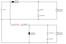
That looks like 6" bass plus 1" tweeter on flattish baffle at 8 ohms nominal. Pretty standard and easy combination. 😀
Either of these will be not a million miles away. Bafflestep to boost the bass level plus some bass rolloff. The second one notches the typical cone breakup of a 6 inch woofer.
The red resistor adjusts tweeter level. The first one is easier and kinda an industry standard. I'd prefer the smoother sound of the second. 😎
Oh, it's a 3kHz crossover. Anything lower is silly unless you really know what you are doing.
Attachments
Last edited:
That looks like 6" bass plus 1" tweeter on flattish baffle at 8 ohms nominal. Pretty standard and easy combination. 😀
Either of these will be not a million miles away. Bafflestep to boost the bass level plus some bass rolloff. The second one notches the typical cone breakup of a 6 inch woofer.
The red resistor adjusts tweeter level. The first one is easier and kinda an industry standard. I'd prefer the smoother sound of the second. 😎
Oh, it's a 3kHz crossover. Anything lower is silly unless you really know what you are doing.
Well it's an 8", and you're designs look to assume an 8ohm driver on each circuit. Neither speaker are 8ohms, in fact at the 3kHz point you suggest they're 18 and 14ohms respectively. Also, the woofer's response starts to fall off at 2kHz so I don't know why you think crossing at 3kHz would be better - can you please explain?
I take it you ignored my request for a phase linear design? I was just reading A Bessel Filter Crossover, and Its Relation to Others and it seems to offer some phase linear solution formulas. It also mentions the fourth-order Linkwitz-Riley filters are in phase at the output. Which filter designs are these you've put together?
Also I only see the bass attenuation on the second diagram you've given - am I reading the circuit correctly or is that a boost?
I should mention that the frequency measurements taken were all nearfield measures.
I just re-read my own post. Maybe I need some coffee or something to cheer me up, but my rudeness is totally uncalled for. Sorry about that.
Thank you for posting a suggestion. I'd really like to fully understand it - thus the rigorous questioning.
Thank you for posting a suggestion. I'd really like to fully understand it - thus the rigorous questioning.
You didn't mention whether you want to build an active or passive crossover (at least I didn't see that).
If you want to build an active crossover, you can design it using my Active Crossover Design tools. These are Excel spreadsheets but use only formulas (no VBA macros) and I have used them under Open Office Calc and they work exactly as advertised and so they should be fine under Libre Office as well (I assume).
the Active Crossover Designer web page
You mentioned Bessel crossovers and a phase linear design. I'd caution you to not overlook the fact that the driver has its own phase response because it is like a bandpass filter (albeit an electromechanical one). You should take into account the driver phase when doing the crossover design, or you can have very different results (in the frequency response) than you are intending/expecting. Also, Bessel filters are a poor choice for a loudspeaker crossover. They have very low slopes, even at high order. When your tweeter is distorting because it is being forced to reproduce relatively low frequencies with too much power, you will no longer be worried about phase linearity!
-Charlie
Hey Charlie,
I think a passive is the method I'm leaning toward here. I don't have money to buy matching amps at this point.
Am I mistaken in thinking that I've already measured the phase of the drivers and found them to be both linear and matching?
I think a passive is the method I'm leaning toward here. I don't have money to buy matching amps at this point.
Am I mistaken in thinking that I've already measured the phase of the drivers and found them to be both linear and matching?
Hey Charlie,
I think a passive is the method I'm leaning toward here. I don't have money to buy matching amps at this point.
Am I mistaken in thinking that I've already measured the phase of the drivers and found them to be both linear and matching?
Is this the phase response(s) you are talking about?
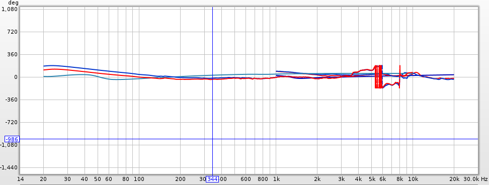
It's difficult to tell what is going on. The scale is way off - phase is usually plotted with a min of -180 degrees and a maximum of 180 degrees, since this corresponds to the wrapped phase that you often get out of a measuring program. If you "zoom out" too far, everything starts to look like it's about at zero, and linear.
I would call only these "matching" phase angles if the phase was within 15 degrees over the band in which you will implement the crossover. For a Bessel crossover at 1.8kHz this will extend from something like 180Hz to 18,000Hz (the -40dB down points for the HP and LP filters).
Also, what are you plotting in the phase plot?? Measured phase? Minimum phase? Can you rescale the y-axis and repost the plot (keep the same x-axis scale). That will clarify the phase situation...
-Charlie
Wow, don't know why I didn't catch that scale issue. 😱

Turns out they're not that linear or matching.
I've taken out the measurement with the Rhode as I trust the Josephson mic a little more and the lines are hard enough to follow without extra measurements.
The phase here is what REW has measured on impedance measurements and nearfield mic measurements.
Wow, don't know why I didn't catch that scale issue. 😱
View attachment 342675
Turns out they're not that linear or matching.
I've taken out the measurement with the Rhode as I trust the Josephson mic a little more and the lines are hard enough to follow without extra measurements.
The phase here is what REW has measured on impedance measurements and nearfield mic measurements.
Ah, thanks. Now let's see...
I'm not sure that I like how the phase climbs from around zero up to +180 degrees for one of the series. That's not really physically possible. Phase is a quantity that can only get progressively more negative with increasing frequency, apart from a little wiggle here and there. Also, it seems to be hovering around zero too long (compared to what I have seen for a typical midbass drive unit). Was there some kind of delay subtraction or auto-zero of the impulse peak done?
Anyway, to cut to the chase, it's best to use a loudspeaker crossover design package because it will take into account all the things that influence the speaker's frequency response, be it driver impedance & phase, acoustical amplitude (e.g. SPL) & phase, or the reactances of the components in the crossover. If you absolutely cannot find any software for your O/S in which you can account for all of these things, you might try posting your situation on the Parts-Express Tech Talk forum. LOTS of knowledgeable DIY loudspeaker designers hang out there and someone will help you (if you do a little groveling) by designing the crossover for you using PCD or other software (if you ask nicely). They can also help you with the measurement side of things, too. Once you see the whole process done right, you can try to do it yourself with confidence that you won't be wasting your time/money.
-Charlie
I just took some SPL measurements with REW and this is the phase response it tacked onto the driver - the impedance measurement is separate and REW had no idea they were even from the same driver. I'm not aware of anything in the measurement process that would account for the phase issue you describe - maybe the phase of the microphone used has altered things?
I don't have an SPL meter here to accurately bias my microphone measurements, so I'll have to do that by ear.
I am able to get the ARTA suite up and running through WINE on my OS. Will that work, or should I just head over to Parts-Express and do this there?
I don't have an SPL meter here to accurately bias my microphone measurements, so I'll have to do that by ear.
I am able to get the ARTA suite up and running through WINE on my OS. Will that work, or should I just head over to Parts-Express and do this there?
I just took some SPL measurements with REW and this is the phase response it tacked onto the driver - the impedance measurement is separate and REW had no idea they were even from the same driver. I'm not aware of anything in the measurement process that would account for the phase issue you describe - maybe the phase of the microphone used has altered things?
I don't have an SPL meter here to accurately bias my microphone measurements, so I'll have to do that by ear.
I am able to get the ARTA suite up and running through WINE on my OS. Will that work, or should I just head over to Parts-Express and do this there?
You really only need accurate SPL data. Do a nearfield and a gated impulse response or other kind of farfield measurement on the woofer. Do a farfield measurement on the tweeter. The SPL from these will need to be "processed" into a minimum phase measurement and the phase will be calculated from the SPL response. This means that you don't need to worry about what the phase looks like now.
I would get the best SPL measurements you can for each driver and then go over to PE Tech Talk for help. The first question they will probably ask you is whether you used a calibrated microphone to make the measurements, which you didn't. This means all your SPL data may be off by 1-2dB, especially For the tweeter, so the final result will be in question there but might be OK anyway.
If you can swing it, sell your existing mics and get a calibrated measurement mic. For $90 you can have one:
Dayton Audio UMM-6 USB Measurement Microphone* 390-808
Cross·Spectrum - Calibrated Dayton Audio UMM-6 Microphones for Sale
This calibrated mic plugs into your computer via the USB port, so you don't need a mic preamp.
I use ARTA and wrote a tutorial on it, so I can highly recommend the software:
http://audio.claub.net/tutorials/FR%20measurement%20using%20ARTA.pdf
Welcome to speaker building. It can become addictive...
-Charlie
I certainly don't plan on selling any of my current mics. I also don't plan on buying a USB mic as I have a clean and nice pre-amp presonus soundcard that a USB mic won't manage to match.
I've actually been debating if I should get a nice cheap Dayton EMM-6 or if I should splurge on a Josephson C550 http://www.josephson.com/pdf/srs5.pdf that won't deviate as much over the years. Any opinions?
Either way, don't I still need a SPL meter before I can make reliable SPL measurements?
I notice you're ARTA tutorial doesn't go into crossover design. Does that software have those capabilities?
- Status
- Not open for further replies.
- Home
- Loudspeakers
- Multi-Way
- My first crossover design (yes I've measured things - even phase) Bessel?