There could be two problems.
Check the voltage at the output. It could be as low as -11Vdc.
Increase R8 until output ~50%Vss
R6 supplies collector current for Q3 and base current for Q2. I normally aim for 10% to 50% of Ic Q2 to let Q3 operate properly.
You have ~0.5%
Try R6<1k
To get you and your circuit working, reduce your FET bias current to ~100mA. It will drive headphones quite well at this level while you experiment with component values to find out what each does to performance.
Thank you so much Andrew. The source voltage on the FET was so low that Q2 was going into saturation on the negative signal peaks. I already have the board soldered point to point on perf-board, so I couldn't raise R8, instead I lowered R7. I then lowered R6 to an appropriate value and all is well with the world. Strangely enough the amp sounds significantly better when it is functioning properly 😉 .
The hum persists.
At this point I am sure that lots of fiddling could improve things slightly, but it is due tomorrow and I am going to call it finished for now. I will try to post a few measurements and the schematic with finished values later today in case anybody is interested.
Thanks again,
Chad
I still don't think you have the ccs working right. Your R9 is what sets the current. Assuming .6 volts, your 2.35R R9 should be passing about 255ma. R6 needs to be adusted to give the 10%-50% of the 255ma. If you set R6 too high, the ccs is simply not operating as intended. I would suggest another test where you set R6 to a much lower value like 220R. This will allow enough current to flow through the transistor on the left. Good luck!
Joel
Joel
Sorry, I am not being clear. I had tried lower values for R6 before, but it caused major stability problems. It turned out that the problem was that the DC bias of the FET was causing Q2 to leave active mode. By raising the DC gate voltage I was able to get the whole thing working as expected.
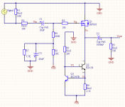
jgray: you are absolutely right. The CCS was definitely not working right in the last schematic. The voltage drop across R9 was only 0.2V, I am surprised it worked at all. The new values in the schematic below seem to be working properly.
Thanks for the help!
Chad
jgray: you are absolutely right. The CCS was definitely not working right in the last schematic. The voltage drop across R9 was only 0.2V, I am surprised it worked at all. The new values in the schematic below seem to be working properly.
Thanks for the help!
Chad
Attachments
So I got everything up and running, but I was still not happy with the measurements. I haven't been able to do any distortion or frequency response testing yet, but my scope shows a lot of HF noise. Investigating I found that the wall wart power supply I am using (12v 1.5A) is really noisy! Here is the frequency of the main switching noise:
And here is a detail of the switching transient:
Notice that the peak-to-peak on the transient is about 0.5V. I knew that these wall-warts were noisy, but that seems excessive. The question is this: how audible do you think this will be? My goal is to put this in a box over christmas break so I can leave it hooked up next to my computer. I was planning on just using the wall wart, but I am wondering if perhaps I should build a simple PS instead. Do you think a simple linear supply would provide an improvement in sound quality?
Thanks,
Chad
Attachments

I cannot hand on heart say that switching supplies sound worse than linear supplies when both are competently designed to match the load.
I can say it is easy to get fairly good results from linear supplies. And some get excellent or better results from linear supplies
I can say it is easy to get fairly good results from linear supplies. And some get excellent or better results from linear supplies
- Status
- Not open for further replies.