i suspect the chip already damaged .
or you can try p2p to make sure the chip its ok ,just need some resistor and caps 🙂
or you can try p2p to make sure the chip its ok ,just need some resistor and caps 🙂
Hi,
I have been following this thread and I have the following question. Why the negative capacitors in the power supply board doesn't get hot? Just the ones in the amp board. It is possible bad caps.
I have been following this thread and I have the following question. Why the negative capacitors in the power supply board doesn't get hot? Just the ones in the amp board. It is possible bad caps.
i suspect the chip already damaged .
or you can try p2p to make sure the chip its ok ,just need some resistor and caps 🙂
How can we measure if the chip(s) are bad sir ?? I have very little experience with it, have no experience for point to point either 😕
Hi,
I have been following this thread and I have the following question. Why the negative capacitors in the power supply board doesn't get hot? Just the ones in the amp board. It is possible bad caps.
I think mooly is right, my meter have problem for reading AC in CD current (cheap meter issue), the cap at power board dosen't get hot at all, or maybe just bad layout ?
Hi,
Can you make test by disconnecting the wires from the power supply to amp board. Turn on the power supply and let it run to see if the negative capacitors get hot.
Can you make test by disconnecting the wires from the power supply to amp board. Turn on the power supply and let it run to see if the negative capacitors get hot.
Hi,
Can you make test by disconnecting the wires from the power supply to amp board. Turn on the power supply and let it run to see if the negative capacitors get hot.
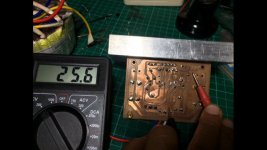
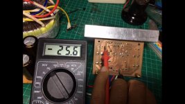
Nope, they are not getting hot, even if i plug 32-0-32AC, their DC current are correct, 24-25vdc at 18ac, and 43-44vdc at 32ac sir, it can run all night and not getting hot at all
How can we measure if the chip(s) are bad sir ?? I have very little experience with it, have no experience for point to point either 😕
Measure between negative and positive PS,between negative and output,negative and ground.Lm 3886 must be off board.
None of this makes any sense.
You could remove the four large caps and then test the amp board. There is more than enough capacitance on the PSU board for it to work.
Just add a small (say10uf) cap across each of those 0.1uf rail decouplers close to the chip.
Get the amp working, then we can sort the other caps out.
You could remove the four large caps and then test the amp board. There is more than enough capacitance on the PSU board for it to work.
Just add a small (say10uf) cap across each of those 0.1uf rail decouplers close to the chip.
Get the amp working, then we can sort the other caps out.
None of this makes any sense.
You could remove the four large caps and then test the amp board. There is more than enough capacitance on the PSU board for it to work.
Just add a small (say10uf) cap across each of those 0.1uf rail decouplers close to the chip.
Get the amp working, then we can sort the other caps out.
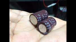
I remove 4 1000uf Cap and test the amps, lightbulb bright slightly and there is dc voltage at speaker output, and now, the chips who start warm, im afraid to damage the speakers & my phone if i connect it to speaker lol
There i upload image cap that i remove from right & left amp, the left cap seems normal, and right cap that get hot are start to swollen
Attachments

Last edited:
You mustn't connect speakers yet.
Now set your meter to DC volts and put the black on the main power supply ground. Confirm that pins 1 and 5 have POSITIVE 20 volts (whatever your supply is) and that pin 4 has a similar NEGATIVE voltage present.
If that is OK then you are really getting into needing to look at this with an oscilloscope to see what is happening.
if his supply voltage from the transformer is 24 and he's measuring 54 vac at the supply board terminals that would suggest a shorted diode in the main bridge. ripple+ dc is the only thing that i can think of that would put the reading that high no?
it doesn't change the possibility that his chip is cooked.
it doesn't change the possibility that his chip is cooked.
His AC readings were odd showing voltages with the meter leads one way around and not the other. What read 54vac one way about read zero the other and vice versa. That seems to be an artefact of the cheap DVM.
Hi,
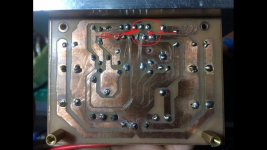
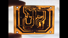
Attached it is one of your picture showing the back of the amp board. By enlarged it using Paint shop something look suspicious like you have a bridge between the positive and the negative pin. Would you please check it to see if there is a bridge or not.
Attached it is one of your picture showing the back of the amp board. By enlarged it using Paint shop something look suspicious like you have a bridge between the positive and the negative pin. Would you please check it to see if there is a bridge or not.
Attachments
Is there a chance that some of the capacitors have the jacket and it's negative symbol on the wrong way around?
any ac at the speaker output?
My ugly meter reading ac at dc current sir,
Hi,
Attached it is one of your picture showing the back of the amp board. By enlarged it using Paint shop something look suspicious like you have a bridge between the positive and the negative pin. Would you please check it to see if there is a bridge or not.
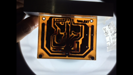
It looks good at my meter & under the light sir, its only the flux that i havent clean it yet, pls have a look at pic
You mustn't connect speakers yet.
Now set your meter to DC volts and put the black on the main power supply ground. Confirm that pins 1 and 5 have POSITIVE 20 volts (whatever your supply is) and that pin 4 has a similar NEGATIVE voltage present.
If that is OK then you are really getting into needing to look at this with an oscilloscope to see what is happening.
Its reading 24-25 vdc sir, pin 1&5 , 4 are directly from the power supply board, the current are following my psu,
Is there a chance that some of the capacitors have the jacket and it's negative symbol on the wrong way around?
If only i blowing one cap i believe the case is posible, but until now i have blown 3 caps & damaging other 3, i believe the symbol are on the right way air
Should i change layout sir ?? I contact designer of this layout, and himself havent build this amp yet
Attachments
Last edited:
Hi,
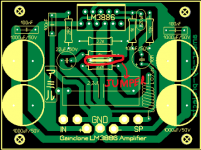
Did you install the jumper showed in attached picture? This jumper it is needed to output to the speaker. The reason I asked is because your speaker voltage reading is zero volts.
my speaker voltage reading 19volts sir, yes i install the jumper, wierd situation
Hi,
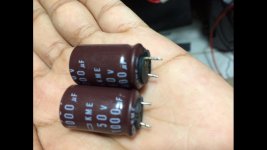
Sorry I asked too many questions. Does the capacitors used in the power supply same as the one installed in the amp board? The power supply caps looked larger than the ones used in the amp board.
Sorry I asked too many questions. Does the capacitors used in the power supply same as the one installed in the amp board? The power supply caps looked larger than the ones used in the amp board.
If you have an ESR meter, be sure to check your caps' ESR. I do agree that it can be a bridge issue as there's no negative side issues and loads of positive ones. Hence why there's 20v-dc on the output. There's no contraload.
If you don't have a spare diode bridge you can make one from four suitably rated diodes in a square all pointing at each others ends.
If you don't have a spare diode bridge you can make one from four suitably rated diodes in a square all pointing at each others ends.
Its reading 24-25 vdc sir, pin 1&5 , 4 are directly from the power supply board, the current are following my psu,
Those readings look OK and the polarity matches your first photo.
Without having this in front of me I can't guess at what is going on and why those caps are blowing up.
- Status
- Not open for further replies.
- Home
- Amplifiers
- Chip Amps
- My first amp & its blown (need help)