Hi...
If i have a look to your schematic, i can see that input ground and supplyground is the same. If i make a pcblayout i split the grounding of the input with one 10 ohm resistor. You can try to solder an 10 ohm resistor to rca ground and the other end to the original ground shielding. Inputground is splitted then and provide a groundloop over Cinch/RCA...cheap try...
If i have a look to your schematic, i can see that input ground and supplyground is the same. If i make a pcblayout i split the grounding of the input with one 10 ohm resistor. You can try to solder an 10 ohm resistor to rca ground and the other end to the original ground shielding. Inputground is splitted then and provide a groundloop over Cinch/RCA...cheap try...

Since the post #32, the DIY amplifier is physically on my granite kitchen countertop, and is connected to nothing else than the speakers 8 Ohms resistors and the headphone in parallel.With the test shown on slide 40, all other equipment must be off so you can be absolutely sure the issue is your amp, and not HF radiation from some other piece of equipment.
Yes I already have read them. Thank you very much! Effectively my problem is very close to the slide #40. I tried to disconnect both Input connector from their respective Amplifier PCB and I don't hear any noise. Then I made two long cables with the same microphone shield cables. I connected them to the input amplifier while I was keeping them outside of the case. No noise. When I move the cable around the transformer, of course I hear the noise louder but my concern is that it is the exact same noise frequency of my original problem. So I am wondering if the problem is not related to the transformer that irradiate.1. See slides 30-39 in my post above which explain how a cross-channel ground loop forms. It's no good just putting the connectors together if you do not minimise the total loop area available for coupling inside the amp. Then see slides 61-64 which show how to route the internal input cabling to minimise the cross-channel loop area. You can experiment with cable placement to get the noise down - just listen for the quietest positions.
The actual path of my cables is already the better place where I could achieve the lowest noise, choose fro the headphone noise level. Regarding the RCA connectors that should be the closest possible with their grounds tied together, in my setup there are two wires from the ground lug of the RCA connectors that goes to the HQG on the case. If I unconnected them the noise is louder.
My two bridges, the power supply and protection, are already snubbed with 0.1uF capacitors.3. As an added precaution, you should snubber your rectifiers - a good general-purpose value is 22 Ohms and 0.1uF ceramic. Rectifiers can ring at 100's kHz up to MHz when they turn off due to the rectifier capacitance and the cabling inductance.
I will try that...2. RFI/HF interference. Where the input connectors come into the chassis, bond the signal grounds directly to the chassis through a ceramic capacitor. Do not use a film capacitor. The cap value should be 50nF-100nF (I show a lower value in the presentation - I have not updated it yet). This makes the cable screens and the amp housing one enclosure to RFI/HF noise. See slides 61-64.
You likely need some resistance too in order to dissipate the stored energy. Resistors go in series with the caps....already snubbed with 0.1uF capacitors.
Tried it without better results... Thank anyway...You can try to solder an 10 ohm resistor to rca ground and the other end to the original ground shielding. Inputground is splitted then and provide a groundloop over Cinch/RCA...cheap try...
But for the good news, I fixed my problem!
I rerouted both input cables, passing them just along between the heat-sinks and the Amplifier PCB. While making the tests, I forgot that I was still doing it with the headphone, and my mind was seeking NO noise. As Bonsai document explain, the headphone are much more sensible than the speakers. I reach a level where without the RCA loop cable, both amplifiers were totally free from noise, except for the white noise that is normal, while with the RCA loop cable I still could hear a little noise. Tired, I choose to close the amplifier and leave with it like this, hopping that the noise would be a bit better.
Surprise, with all the gears connectors connected, the right speaker is totally silent. I could absolutely not detect any noise. The left speaker has a little noise, but so low that as soon as I remove the hear from the tweeter, I could not hear it! This latest probably come from the AC plug as the Input cable pass just below it.
I am much more happy now with my project 🙂
And I wanted to thank every one who help, Honestly, that is so much appreciate.
@Bonsai, I will study much deeper your document 🙂 Thank!
Attachments

Very interesting. However well shielded, a magnetic field will induce a current, and therefore voltage - in an earth screen etc: My recent revamp of an Old Sony led to a very quiet amplifier - and now I have thought of a possible connection that may assist you.I rerouted both input cables
In my design I was looking for a way to conveniently mount the toroid, and I ended up with a strong metal L bracket, that put the toroid on it's side (with a wooden mandrel to support it in the centre), and shields the internals of the amplifier with the metal bracket.
So if you have space, I can recommend to shield the transformer.
Just a simple grounded barrier between the transformer and PCBs may help.
I also use a mains filter (built into the input IEC socket) so no RF gets into the primary.
Attachments
Agree you can get a lot of conducted HF on the mains from other equipment that uses SMPS, or has un-snubbered transformer/rectifiers. I measured the common mode bandwidth of a large toroid and it was flat out to 3 MHz. In series mode, it was flat out to 200 or 300 kHz.
I’ve found an interwinding screen (which you connect to earth) and a 0.1uF 275V ‘X’ cap across the mains at the IEC connector can also offer substantial noise reduction.
I measured the interwinding capacitance on a 1.2 kVA transformer and it was over 1 nF, but with the screening dropped to under 100 pF - a pretty useful 10x reduction.
(See Mark Johnson’s thread on transformer snubbers here https://www.diyaudio.com/community/...rmer-snubber-using-quasimodo-test-jig.243100/)
For toroidal transformers the radiated field is primarily around the outside so field will cut into any electronics mounted either side. When you mount it vertically and oriented front to back (not side to side), the radiated field is lower. The housing will also trap a lot of the field, helping reduce noise. I usually mount my transformers flat, but if vertical brackets were available and size permitting, I’d mount vertically.
Last edited:
You mean like a bigger donut, surrounding the smaller donut (the toroid) ?For toroidal transformers the radiated field is primarily around the outside
Very interesting info, and I was amazed at the bandwidths!! Thanks.
Quick question to Bonsai...
I have finished to read your presentation document. In my very first wiring setup I twisted the three cables +50VDC/GND/-50VDC with gauge 16 wires. Then I read back a comment in my book "High-Power Audio Amplifier Construction Manual" from G. Randy Slone;
I quote:
So I choose to redo my wiring, this time only twisting the +50VDC and -50 VDC together, while laying the ground wires on their own under the aluminum plate that serve to fix the transformer and the Power Supply PCB.
Seeing that untwisting the three wires from the first wiring setup have damage the jacket of the wires, I had to order new cables to redo the new setup.
Now I am reading from your document, at page 19, that the First Line Remedy is, and I quote:
So I am confuse. Should I twist all three wires together or just the +50/-50 VDC ?
I have finished to read your presentation document. In my very first wiring setup I twisted the three cables +50VDC/GND/-50VDC with gauge 16 wires. Then I read back a comment in my book "High-Power Audio Amplifier Construction Manual" from G. Randy Slone;
I quote:
The positive and negative rail voltage wires (running to the individual amplifier PC boards) should be twisted together and kept away from other sensitive wiring. Do not twist these around the individual power supply ground wires running to the PC boards. Keep individual ground wires separate and physically removed from the rail voltages wires.
So I choose to redo my wiring, this time only twisting the +50VDC and -50 VDC together, while laying the ground wires on their own under the aluminum plate that serve to fix the transformer and the Power Supply PCB.
Seeing that untwisting the three wires from the first wiring setup have damage the jacket of the wires, I had to order new cables to redo the new setup.
Now I am reading from your document, at page 19, that the First Line Remedy is, and I quote:
Keep LOOP AREAS as small as practicable
and especially those carrying significant
current by twisting together ground and
signal wiring, and 0V supply wires with the
+ and – supply to modules. Keep sensitive
circuits away from high current circuits.
Use good quality interconnects (braided
shield) with low interconnect resistance
and high contact force connectors
So I am confuse. Should I twist all three wires together or just the +50/-50 VDC ?
Set the volume to 1 watt with Rotel.amp
Turn off and connect DIY amp then power on.
If it is louder your amp has more gain and hence is amplifying the noise
Turn off and connect DIY amp then power on.
If it is louder your amp has more gain and hence is amplifying the noise
There is a page in Bonsai's document that looks like this:

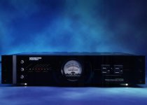
Here's a pic of the inside a Marantz MA9S2 mono block power amp:

See any resemblance?
Here's a pic of the inside a Marantz MA9S2 mono block power amp:
See any resemblance?
Yes.Should I twist all three wires together
This is ambigious 😀Keep individual ground wires separate
If you have individual ground wires for pre-amp etc - these should be away from the main supply wires, yes.
The 'twisted pair' effect keeps the magnetic flux within the send and return wires. With the AC1, gnd and AC2, actually most current will be just travelling up and down the AC wires only, the ground only having a small current. Because the AC currents cancel in the twisted pair, no real voltage is generated in the braided earth travelling with it.
But any time a +ve or -ve side power draw happens, that power draw will be via the AC1 and Gnd wire or AC2 and gnd, so that forms it's own little loop, but again, that's cancelled. So braiding the 3 together is the correct way.
The same applies to the DC to the output transistors and amplifier, these wires are also, ideally, close and twisted, so the music pulses balance too, keeping the magnetics low, and also making them less susceptible to pickup (the cancellation works both ways) - but this can be more difficult to arrange. Just bear in mind a power amplifier with a half turn of wire connecting the +ve or -ve is also an electromagnet and those current paths can generate magnetic fields, which will generate voltages in nearby things, so try to keep the +ve,. -ve and grounds close on the PCB too.
So always keep the power and ground braided, yes, so the currents stay within that assembly.
Man, this is weird...
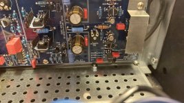
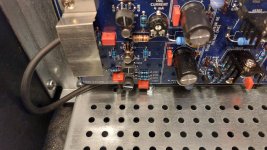
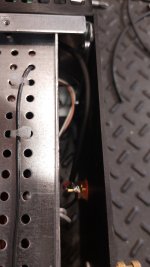
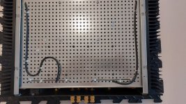
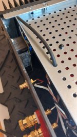
I decided to try to make a better path for the Input cables. I though it would be a good idea to make a couple of holes bigger in the grid aluminum panel in order to be able to pass the wires under this panel, in the hope to have them shielded more from the transformer. This was my first first idea but I never concluded it because the holes of the panel wasn't bigger enough to let the wires go through. I also used a gauge #14 wire to join both RCA Input grounds together, and soldered a center tap connected to the HQG.
So again with the headphone I organized the wires path to minimize the noise while having both RCA Inputs joined with an external cable.
Now, with the DIY amplifier connected to the speakers and with the RCA cable loop connected, I have better result. The right channel is as quiet as yesterday and the left channel noise seem lower then yesterday. Great I though!
But then, once the pre-amplifier gear is plugged in, the noise is back on both channels! Even if it is very low, how come could be present when the RCA loop result is quiet?!!
Attachments

you may need a ground lift resistor between psu 0v and chassis ....... see bonsai's documents for the details
Also, if the PSU caps are big enough, get it sizzling, then pull the whole plug out of the mains (beware of pops!) and see if it goes away.
If so, the noise is getting in via the safety earth or the AC line - the AC line can probably be isolated (mainly) by switch it off - ideally via a double pole switch - and seeing if the sizzle is still there as the caps run down.
The noise must be coming from somewhere 😀
If so, the noise is getting in via the safety earth or the AC line - the AC line can probably be isolated (mainly) by switch it off - ideally via a double pole switch - and seeing if the sizzle is still there as the caps run down.
The noise must be coming from somewhere 😀
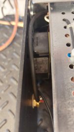
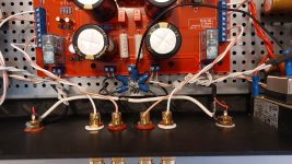
I just redo the +50/0/-50 VDC cables from the Power Supply to the Amplifiers boards. This time by twisting the three cables together. This upgrade make me realized that the 12mm M3 screw that was keeping all the GND lugs to the HQG Hex Standoff was to long. When I screw it until it reach the end of the Standoff hole, the lugs were still loose!
So I replaced the screw with a 8mm M3. They are now tighten.

With nothing at the Inputs, both channel are totally quiet.
With a RCA loop cable, both channel have very very low noise, each channel at the same level. I really need to get my hear near the tweeter to hear the noise.
With the Pre-Amplifier gears connected, same as with the RCA loop, but a tiny louder, still much lower than before this upgrade.
So I replaced the screw with a 8mm M3. They are now tighten.
With nothing at the Inputs, both channel are totally quiet.
With a RCA loop cable, both channel have very very low noise, each channel at the same level. I really need to get my hear near the tweeter to hear the noise.
With the Pre-Amplifier gears connected, same as with the RCA loop, but a tiny louder, still much lower than before this upgrade.
Sizzle noise is usually from a bad component, bad connection, or else from AC line noise. A good power conditioner can make a significant difference if AC line noise is the cause. Best conditioner for audio I know of was designed by a couple of members of this forum: Richard Marsh and Demian Martin ( @1audio ). They designed it for Monster. It was produced in different versions with last one being the best. Sometimes you can find them used on ebay, "Monster HTPS 7000 MkII Signature Edition." The best ones have three GFI duplex outlets on the back for the transformer balanced AC line outputs. The earlier versions of the HTPS 7000 were also effective at power conditioning, but didn't have the additional GFI safety feature.
Well, I reverted my wires path to the same as post #44. It was the best setup vs noise I got since the beginning. I kept the left wire under the grid aluminum panel until it reach the PCB in order to minimize the AC plug induction, then past it along the PCB between it and the heat-sink.
I got very close results as post #44. Silent with no Input, a very low noise this time with the RCA loop cable, but practically unperceptive. Same practically unperceptive noise on the right channel with the pre-amplifier gears connected, while a very acceptable noise on the left channel. This channel is always the one who must past close to the AC plug. I guest this AC plug is to close to the left side of the panel. Of course one radical solution would be to redo the rear panel to cis-convert this.
I got very close results as post #44. Silent with no Input, a very low noise this time with the RCA loop cable, but practically unperceptive. Same practically unperceptive noise on the right channel with the pre-amplifier gears connected, while a very acceptable noise on the left channel. This channel is always the one who must past close to the AC plug. I guest this AC plug is to close to the left side of the panel. Of course one radical solution would be to redo the rear panel to cis-convert this.
Attachments

- Home
- Amplifiers
- Solid State
- My DIY Amplifier has a small sizzling sound