My goal is to stay with discrete components. I hate SMD/SMT. The bridge rectifier is a Vishay GSIB1520-E3/45, 200 Volt 15 Amp 300 Amp IFSM.You'll also get a nice / further improvement by swapping the rectifier for one of the Avondale SMT Schottky items
I can't say that I like the look of the printed brown/ gold labelling on those caps, it's not what Nich FG used to look like.
Good luck
Good luck
Those aren't Fine Gold (FG) type. Those are Gold Tune (KG) Type-III !I can't say that I like the look of the printed brown/ gold labelling on those caps, it's not what Nich FG used to look like.
https://partsconnexion.com/collecti...3vdc-kg-gold-tune?_pos=1&_fid=647ee0014&_ss=c
Attachments
In my house in America, built in 1930, I only have a few correctly grounded wall sockets. Was chasing noise in a phono stage and discovered this by moving from room to room. When the nose level dropped after plugging in to the socket connected to the mains fuse box, I discovered via multimeter that many outlets were improperly or not really grounded. I connect all audio devices to a single properly earthed outlet now and have eliminated my noise problem.
Also: Have you tried an IEC with an integrated filter?
Also: Have you tried an IEC with an integrated filter?
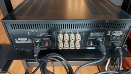
I live in a condominium build in 2015. This kind of IEC with filter and fuses AC plug is exactly what I am using. See attached below...Also: Have you tried an IEC with an integrated filter?
Attachments


I like @Globulator ’s post 17 and @Thekak ’s comment.
As a diagnostic test, not a permanent solution, I suggest lifting the safety ground connection to the diy amp chassis, perhaps using a 3 wire to 2 wire adapter at the power plug. Exercise due caution. If hum symptoms improve, then the shorted diode bridge isolating signal ground from safety ground may be a solution.
Remember to disconnect scope for experiment. It’s yet another ground loop trouble-maker.
Last edited:
From the look of the scope traces you are picking up radiated AC line harmonics when you connect the RCA cables to a source device. Could be that what is happening is that when you connect the cables at the source end, then the grounds of the RCAs are connected together at the source end and thus form a ground loop antenna that picks up the noise. Mode conversion from cable ground current to amplifier differential input voltage may account for the rest of the noise coupling mechanism.
Following your suggestion, I had this plug in my stock and did the test:I like @Globulator ’s post 17 and @Thekak ’s comment.
As a diagnostic test, not a permanent solution, I suggest lifting the safety ground connection to the diy amp chassis, perhaps using a 3 wire to 2 wire adapter at the power plug. Exercise due caution. If hum symptoms improve, then the shorted diode bridge isolating signal ground from safety ground may be a solution.
The noise is still present but had improve about by half to my hears. Notice that it is already pretty low in volume without the plug. So what the bridge diode solution trick would look like? Any schematic to better picture it in my mind?
Interesting. Do you have any suggestion trick to fix this?From the look of the scope traces you are picking up radiated AC line harmonics when you connect the RCA cables to a source device. Could be that what is happening is that when you connect the cables at the source end, then the grounds of the RCAs are connected together at the source end and thus form a ground loop antenna that picks up the noise. Mode conversion from cable ground current to amplifier differential input voltage may account for the rest of the noise coupling mechanism.
Best to find the offending source and see if it can be fixed.
Could also be the RCA cables form a larger loop area than necessary. Could be they are longer than necessary, and or they are routed too far apart from each other, and or too close to some noise source.
Could also be the RCA cables form a larger loop area than necessary. Could be they are longer than necessary, and or they are routed too far apart from each other, and or too close to some noise source.
Beautiful work!
this could be the root of the problem, the layout is typical of diy amps.
the physical separation of the left / right input signal creates a loop area.
(probably made worse by having the pcb inputs at the opposite end of the chassis to the input sockets)
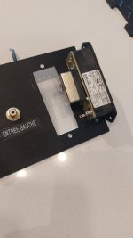
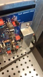
Here is one question I have in mind. If you look carefully at the picture above, my amplifier board was designed to have the HQG at one end near the +50/-50 VDC. The Input ground is at the other end of the PCB. When came the time to interconnect everything, I noticed, with the headphone over my hears, that the noise was going a lot lower if I connect the HQG of the Amplifier to the HQG of the case while connecting also the RCA input ground lug onto the case HQG. But I realized that this could make a ground loop if I connect the Input GND with a wire (in my case it is microphone shield cable) at the PCB Input ground also. But if I DON'T connect the PCB Input ground, the noise is worse.this could be the root of the problem, the layout is typical of diy amps.
the physical separation of the left / right input signal creates a loop area.
(probably made worse by having the pcb inputs at the opposite end of the chassis to the input sockets)
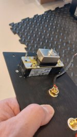
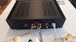
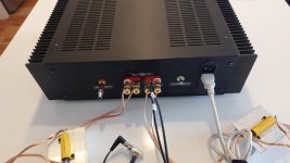
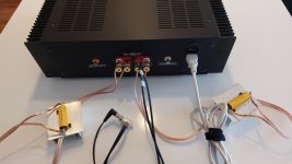
So I just tough to test this again. In the pictures attached below, I have two 8 Ohms/50Watts resistors connected to the speakers terminal and my headphone in parallel. If I don't connect the RCA Male connector with it's hot wire grounded (picture 1), there is no noise. If I connect the RCA Male connector to one channel, the noise is present on that channel (picture 2 and 3).
And I also noticed that my Input tests points (White TP) could be an antenna.
So I try to bring one finger around them and the noise is becoming very loud the closest I bring it. Of course I didn't touch it lol... Then I tried to invert the shield I used at the Input connector to have them cover also the test point (Picture 4). The noise doesn't go up now when I bring my finger close to the test point, even if I touch the shield. But that didn't fixed the noise when a RCA connector is plugged in.
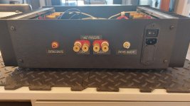
As for the position of the input RCA, I used the Rotel back panel as my inspiration... (Picture 5). The first mechanical design was effectively to have the Amplifier board inverted with the Input connectors close to the RCA connectors, but a huge hum was present because of the close distance between the left channel (ENTREE GAUCHE) and the AC IEC plug :-/
Attachments
Why don’t you make a recording of the offensive noise using your phone up against the speaker and we can then take it from there?
The above poster (#31) has pointed out an important flaw in your amp layout whether it is the root cause of your problem or not.
Never place input connectors on opposite sides of the amplifier rear panel because you create a large loop area that will couple to any noise coming in.
The test for this is to plug a cable from one input to another so it forms a loop. If the amp is noisy with the cable plugged in but not when you unplug one side, you have a cross-channel ground loop.
See the presentation below for more info (I suspect you may have other issues though related to HF noise - see the section about RFI and cable screening).
https://hifisonix.com/wp-content/uploads/2019/02/Ground-Loops.pdf
P.S.: To test this I disconnected temporally one channel and test the other channel with the RCA connector plugged. The noise is still present. So I guess the physical separation of the left / right signal isn't the cause...the physical separation of the left / right input signal creates a loop area.
See post # 20!Why don’t you make a recording of the offensive noise using your phone up against the speaker and we can then take it from there?
Hum, just did the test and it is noisy with the cable connected between both inputs. So I should move one connector closest to the other? Right? I would choose the left connector then seeing that it is close to the AC line. Moving it away, close to the right connector. Does that make sense?The above poster (#31) has pointed out an important flaw in your amp layout whether it is the root cause of your problem or not.
Never place input connectors on opposite sides of the amplifier rear panel because you create a large loop area that will couple to any noise coming in.
The test for this is to plug a cable from one input to another so it forms a loop. If the amp is noisy with the cable plugged in but not when you unplug one side, you have a cross-channel ground loop.
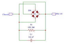
It's simply a parallel connection of a 220nF or similar (X2 maybe) capacitor and a 120Ohm resistor between signal ground and chassis/mains ground.So what the bridge diode solution trick would look like? Any schematic to better picture it in my mind?
As this only gives a weak safety connection, a decent bridge rectifier can also be placed in parallel: using the AC of the bridge pins, with the + and - pins shorted together. This gives a robust 1.4V max difference limit, between signal and chassic ground, for the safety aspect.
Thus some hum is allowed on the earth/chassis, isolated from the signal ground.
This should IMO be soldered near the RCA inputs, as that's the amplifier providing the signal ground for the rest of the gear.
If you read through the document Bonsai linked to in #33, towards the end there are practical examples of what to do.
Regarding the buzzing noise, scope shows it has a repetition period of around 8ms, which corresponds to 120Hz. Repeating spike is likely diode commutation excitation of power transformer leakage reactances. Snubbers may help reduce that type of noise production. However, that's not the only thing which might warrant looking into. Layout, etc., should probably be fixed as Bonsai document explains.
Regarding isolation of circuit ground from AC line and chassis ground, the following pic shows a common type of "hum-breaker" circuit:

Resistor value may vary in some designs, possibly to as high as 100R.
Regarding the buzzing noise, scope shows it has a repetition period of around 8ms, which corresponds to 120Hz. Repeating spike is likely diode commutation excitation of power transformer leakage reactances. Snubbers may help reduce that type of noise production. However, that's not the only thing which might warrant looking into. Layout, etc., should probably be fixed as Bonsai document explains.
Regarding isolation of circuit ground from AC line and chassis ground, the following pic shows a common type of "hum-breaker" circuit:
Resistor value may vary in some designs, possibly to as high as 100R.
Attachments
Last edited:
Put something like this on each input cable: https://www.amazon.com/Fair-Rite-Ferrite-Split-9-85Mm-100Mhz/dp/B00DK858VA
I listened to post #20. It sounds like you have HF being modulated by mains harmonics which is then demodulated by a semiconductor junction and you then get the buzzing noise. If I understand your problem, you only get this noise when the amp is connected to a source or when you connect the left input to the right input via a cable. With the test shown on slide 40, all other equipment must be off so you can be absolutely sure the issue is your amp, and not HF radiation from some other piece of equipment.
So I’d suggest the following:-
1. See slides 30-39 in my post above which explain how a cross-channel ground loop forms. It's no good just putting the connectors together if you do not minimise the total loop area available for coupling inside the amp. Then see slides 61-64 which show how to route the internal input cabling to minimise the cross-channel loop area. You can experiment with cable placement to get the noise down - just listen for the quietest positions.
2. RFI/HF interference. Where the input connectors come into the chassis, bond the signal grounds directly to the chassis through a ceramic capacitor. Do not use a film capacitor. The cap value should be 50nF-100nF (I show a lower value in the presentation - I have not updated it yet). This makes the cable screens and the amp housing one enclosure to RFI/HF noise. See slides 61-64.
3. As an added precaution, you should snubber your rectifiers - a good general-purpose value is 22 Ohms and 0.1uF ceramic. Rectifiers can ring at 100's kHz up to MHz when they turn off due to the rectifier capacitance and the cabling inductance.
I am assuming in all of the above that your amp is stable and not oscillating. Oscillating at a few hundred kHz will also cause the problems you see, so make absolutely sure your amp is ok.
Good luck!
🙂
- Home
- Amplifiers
- Solid State
- My DIY Amplifier has a small sizzling sound