SimontY,
The EDGE program is a great tool if you keep in mind what it is showing you. It is calculating the effect of the baffle geometry and driver placement as if the driver's SPL were perfectly flat from DC to whatever upper frequency limit you specify. It is not showing you the response of a specific driver in a particular baffle geometry. Other then diameter, you have not told the program anything about the driver so it does not know if the driver response is naturally rolling off consistent with a low Qts value or if the driver response has a peak at fs due to a higher Qts. The EDGE is providing only one piece of the total solution.
If you look at the OB design article on my site, I provide a few plots that show the different contributors to OB response and the final resulting SPL frequency response. If you are set on a passive OB design I also provide some guidance on what types of driver combinations will combine to produce a balanced low frequency response.
Hope that helps,
Martin
The software also can't tell you anything about the reflections of the rear wave. In my limited experience it appears that (with adequate scattering of the backwave) the response is much smoother than one might expect.
Martin,
I wasn't expecting a reply from such a well known speaker designer! Excellent stuff. I've read your PDFs on open-baffle design and found them extremely enlightening. I know now that my next project will be something like a Creative Sound full range driver with high Qts woofer support - the 15" Eminence Alpha if I can somehow fit those in my tiny room. They're extraordinarily cheap drivers. I looked at the 12" version but the Qts is totally different (lower).
I am definitely set on a passive design for this "experiment" as it's a case of proving as cheaply as possible to myself that open baffle can provide a good sound for me, my music and in my room.
I am beginning to see that I need to work on reducing the lower midrange hump, increasing baffle width and maybe even adding wings too to give my low Qts drivers all the help they can get. The only positive thing is having good sensitivity from 4 per side.
I will order some more (larger) coils to set the lower crossover really low (~250hz I think), widen my baffles with cardboard or thin wood and roll off the midrange higher than 300hz.
This is really a bit of fun and these speakers won't be long-term ones.
Thanks
Simon
mashaffer said:The software also can't tell you anything about the reflections of the rear wave. In my limited experience it appears that (with adequate scattering of the backwave) the response is much smoother than one might expect.
Thanks Mike, this is promising. Still, looking at the models as a worst-case scenario (ignoring real driver responses for now) should help make a better speaker.
Simon
I've found an interesting coil to use on my 1st order bass x-over...
1mm wire, ferrite core, cheap, 3.3mH, 1.1 DCR. The added resistance might do something beneficial to the bass response (if someone can tell me how to calculate the change, please do).
This coil would give me a x-over of about 200hz or even lower, which I reckon will help to provide a much flatter summed response. The mid can be brought in to suit.
I'm starting to believe I can make a half decent speaker out of these drivers.
Simon
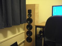
The extra width comes from some 4mm plywood I had from previous poly cylindrical diffusers I had to use in my previous (larger) room. This room's so small diffusion is less important, although I will be adding some shortly. Anyway, the sound is LOADS better now, the bass extending much, much further down. The upper bass is still very peaked, which ruins some instruments and gives a pronounced chesty punch to loud drums! Just need to wait for my 6 inductors now and see what they can do for me.
Simon
Simon
Attachments
Just thought I'd add a word about overall sound quality, in case anyone's reading and wondering if such cheaply and, in fairness, quite randomly made dipoles could sound any good.
They do sound very pleasing, although the upper bass is too loud, and low bass is non-existent. This has the effect of making some material sound great or enhanced, but most songs sound a bit false and the illusion of reality isn't created. Some songs I've played made me smile and realise what I'm in for with open baffles... I've heard some music so vividly presented with a level of detail and dynamic intricacy that I'm simply not used to.
The upper midrange / very low treble (5khz-7khz I believe!) is emphasised and I will attempt to address this with careful crossover values. It makes everything sound over-sweet and coloured.
I will definitely want to go wide range + bass next time, so I only have one crossover to get right!! I'm too lazy to measure responses and do all the work to get it bang on.
Simon
a typical dipole equalization does two things:
1. it raises the bass response to account for the very high roll off of the woofer.
2. it places a notch at the peak that corresponds to the summing of the front and rear waves.
You've attempted to remedy #1 by adding more drivers but haven't addressed #2.
I'd recommend some (at least) basic dipole design guides or software to estimate about where those peaks and dips end up. Perhaps with enough drivers and low and high pass filters, you can get the result you want.
y8s said:a typical dipole equalization does two things:
1. it raises the bass response to account for the very high roll off of the woofer.
2. it places a notch at the peak that corresponds to the summing of the front and rear waves.
You've attempted to remedy #1 by adding more drivers but haven't addressed #2.
I'd recommend some (at least) basic dipole design guides or software to estimate about where those peaks and dips end up. Perhaps with enough drivers and low and high pass filters, you can get the result you want.
Thank you for your very concise response. I am now starting to realise why I have an upper bass peak and that it is normal, and addressing it is a huge part of successful open baffle speaker design.
I have seen a visual representation in the software simulator called Edge, and read several sources of dipole information, including large parts of Linkwitz' website and that of Martin King.
I should have two inductor values to trial in the bass circuit this week, and will also be looking at the addition of side-wings to extend the bass range downward.
Simon
Sounds good.
You can also look at the design a couple different ways.
You can imagine an infinite number of various width baffles such that the summation of all of them is a flat response. Can you approximate this with less than 5 woofers / baffle widths?
You can push the "hump" in response up above the crossover frequency so it's reduced that way. it will change the characteristic of your crossover (Q and F3) so you will have to take that superposition into account. This is probably not feasible since your baffle widths would be only a few inches, but the concept may inspire you.
SimontY said:The added resistance might do something beneficial to the bass response (if someone can tell me how to calculate the change, please do).
Qtsnew=Qts·((Rdc+Radd)/Rdc)
e. g. in your case:
Qts=0,4
Rdc for a 4-Ohmer let us assume 3,5Ohms
DCR of the coil is 1,1Ohm
and get
Qtsnew=0,4((3,5+1,1)/3,5)=0,526
Of course you have to find out, what your woofers DC resistance really is and calculate again with the correct value.
You can increase Qts as much as you like with additional resistors, but you always lose Watts and thus dynamics in them.
y8s said:Sounds good.
You can also look at the design a couple different ways.
You can imagine an infinite number of various width baffles such that the summation of all of them is a flat response. Can you approximate this with less than 5 woofers / baffle widths?
You can push the "hump" in response up above the crossover frequency so it's reduced that way. it will change the characteristic of your crossover (Q and F3) so you will have to take that superposition into account. This is probably not feasible since your baffle widths would be only a few inches, but the concept may inspire you.
Interesting ideas! I did look at what happens if you make the baffle narrow enough but to cancel those peaks would, I think, cause problems elsewhere. Crossing over low seems to be an excellent solution as far as I can see, plus I've been sent VERY interesting information by someone that hasn't made himself seen on this thread!
Originally posted by pacificblue
Qtsnew=Qts·((Rdc+Radd)/Rdc)
e. g. in your case:
Qts=0,4
Rdc for a 4-Ohmer let us assume 3,5Ohms
DCR of the coil is 1,1Ohm
and get
Qtsnew=0,4((3,5+1,1)/3,5)=0,526
Of course you have to find out, what your woofers DC resistance really is and calculate again with the correct value.
You can increase Qts as much as you like with additional resistors, but you always lose Watts and thus dynamics in them.
Thank you pacificblue, this is exactly what I wanted! I think I have some dynamics to spare in these speakers so a fairly high DCR should suit the speakers nicely if that increases the midbass response. I can't find my exact driver DCR but I suspect it's close to 3.5R or maybe a little under.
Simon
The guy who kindly e-mailed me some useful advice was Graham Maynard, who has designed a very impressive looking circuit for passively equalising dipole bass. It's called T-bass, and gives you up to 6dB boost in the low bass, but reduces the upper bass peak [slightly] at the same time. In addition, Graham says his circuit reduces energy storage in the driver, further improving the musicality of open baffle speakers.
The only catch is needing to buy the parts, and he recommends fairly large transformers (as big as 500VA to be on the safe side and avoid core saturation). You also need to use a solid state amplifier of moderate power output (current) as the circuit gives the amp a tougher workout.
I have 180w/4ohm Marantz monoblocks (MA-500) which should be up to the task. I also have some 100VA 25VAC x2 toroids that may well be adequate for a test of the circuit. I have at least four kicking around, so I could even double them up to reduce the resistance and double the power handling. I am generally forced to listen very quietly in this room so I can't see that I'd need big parts (I guess I need to try and see where distortion sets in).
Apologies to Graham if I've misrepresented his circuit here, I think I've written what it does and what some of the pros and cons are. I'll leave it to him to post the actual circuit, but here's a link to the thread on AudioCircle he sent me:
http://www.audiocircle.com/circles/index.php?topic=53322.0
Simon
Pacificblue, I thought that the equation related to Qes only. Wouldn't you have to perform the calculation on Qes and then refigure Qts based on the new Qes?
What you write makes sense. Maybe the formula I quoted is a sufficient approximation. I got this formula from the book "Handbuch der Lautsprechertechnik" by Friedemann Hausdorf from 1990. There is however no hint at restrictions of that formula or at having to go the way you describe.mashaffer said:Pacificblue, I thought that the equation related to Qes only. Wouldn't you have to perform the calculation on Qes and then refigure Qts based on the new Qes?
BTW Mr. Hausdorf is currently chief designer at German speaker manufacturer Visaton.
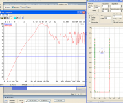
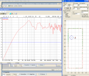
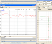
Hi SimontY,
since you are using multiple woofers ...
Just some ideas
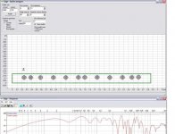
- how to use "edge" to (not quite correctly) take floor reflections
and increase of radiation impedance into account using a
mirror baffle ...
- how to use multiple drivers to circumvent the dipole peak
- how to obtain a smooth LF rollof
Sorry for cutting frequency scale off:
First dark grey line from Left is 50Hz, second is 100 Hz.
Since you have a crossover frequency around 400 Hz,
you will not have to optimize the woofer spacing for
midrange and HF interference patterns. You can as well
check out some equidistant spacings.
Kind regards
since you are using multiple woofers ...
Just some ideas
- how to use "edge" to (not quite correctly) take floor reflections
and increase of radiation impedance into account using a
mirror baffle ...
- how to use multiple drivers to circumvent the dipole peak
- how to obtain a smooth LF rollof
Sorry for cutting frequency scale off:
First dark grey line from Left is 50Hz, second is 100 Hz.
Since you have a crossover frequency around 400 Hz,
you will not have to optimize the woofer spacing for
midrange and HF interference patterns. You can as well
check out some equidistant spacings.
Kind regards
Attachments
- Status
- Not open for further replies.
- Home
- Loudspeakers
- Multi-Way
- My dipole experiment