Hi,
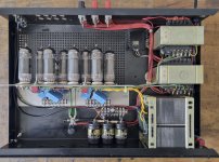
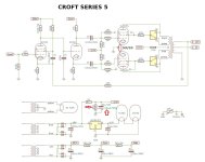
with your kind forum help I finally found a tube amp that I really like: a Croft series 5 with horizontal tubes inside a standard case and SS regulator. It's different from the one shown here (with that schematic). The mains lead was without PE connection, so I lifted GND from chassis through a 22R thermistor and connected PE to chassis. I replaced the 3 small lytics and am waiting for shippment of the 3 main smoothers to replace them as well. It sounds really fantastic! I am trying to figure out the schematic, but it's not so easy as I can't see some resistor color codes well. Please let me know if you think some values are off:

EDIT: updated schematic
with your kind forum help I finally found a tube amp that I really like: a Croft series 5 with horizontal tubes inside a standard case and SS regulator. It's different from the one shown here (with that schematic). The mains lead was without PE connection, so I lifted GND from chassis through a 22R thermistor and connected PE to chassis. I replaced the 3 small lytics and am waiting for shippment of the 3 main smoothers to replace them as well. It sounds really fantastic! I am trying to figure out the schematic, but it's not so easy as I can't see some resistor color codes well. Please let me know if you think some values are off:
EDIT: updated schematic
Attachments
Last edited:

The value of R6 seems wrong to me. The values of R6 and R7 should be equal in this type of phase-inverter. My guess is that R6 is 47K.
The cathode and plate of the lower EL84 are reversed.
The cathode and plate of the lower EL84 are reversed.
Many thanks, corrected the lower EL84 and added photos. Also checked R6 again and you are right, it's a 47K!
Last edited:
Try to put for each cathode of 84 one resistor of 1 ohm 1 watt. Si you can read the bias current for each tube and act as fuse in case of shortPlease let me know if you think values are off:
Walter
It's difficult to fit resistors to each EL84. But I noticed they run quite hot - with my thermal camera I read 200°C (400°F) at the glass bodies of the EL84s. Hope that's OK...?
This circuit uses fixed bias for the output tubes but without a way to measure the bias current or adjust it. It's possible that the tubes are running too hot. As @waltube suggested, I would at least add cathode-to-ground resistors on each output tube so that you can indirectly measure the bias current.
It is not lowHope that's OK...?
Ifyou read the current probably that the 84 works at 100% of anode dissipaton in = class A
The use of cathode resistor help
in addition, if you split also the trimmer for neg voltage bias you can set the current equal for each 84 and, maybe, the OT works better with a perfect balance of bias current
Walter
I do not think the EL84's are running to hot in this amplifier, provided that the voltages in the schematic are correct.
Look at page 7 of this Philips datasheet for the EL84:
EL84 Philips datasheet
The plate current in a pentode is set by the screen grid voltage. In this amplifier the screen grid voltage (Vg2) is about 335 V. The bias (Vg1) is given as -14 V.
Note that on page 7 the difference between curve 1 (for Vg2 = 250 V) and curve 2 (Vg2 = 210 V) is a little under 4.5 squares. So, a difference of 40 V in Vg2 corresponds with a little under 4.5 squares.
The difference in Vg2 between 250 V and 335 V is 85 V. So, to know what a new curve for Vg2 = 335 V would be, one has to shift curve 1 by a little more than 9 squares to the left.
So, with Vg1 = - 14 V, and by shifting curve 1 by a little more than 9 squares to the left, one arrives at a plate current of about 30 mA.
With these numbers the plate dissipation would be about 0.03 x 335 V = 10.05 Watt. Since the maximum plate dissipation of the EL84 is 12 Watt (according to the "Design Centre Rating System"), these numbers seem safe to me.
Note:
The plate and screen voltage in this amplifier exceed 300 V, being the maximum value according the "Design Centre Rating System". But when looking at the values according the "Absolute Maximum Rating System" (in datasheets for the E84L) the maximum plate and screen voltage is 450 V (and the maximum plate dissipation is 13.5 Watt). This explains why there are so many examples of amplifiers in which EL84's/6BQ5's are being run at plate and screen voltages way higher than 300 V.
JPK73
Thanks for providing the schematic. Love Glenn's simple circuits, always sound good too. I had a chuckle at the difference between your schematic and that of Soundmovements, Glenn was always modifying designs although still calling them by the same model, case in point mine and other versions of the Series 7 amplifier. I do have one observation regarding the heat generated is the closeness of the eight EL84 tubes and the inadequate ventilation provided. Once you put that top cover on, must get awfully hot in there. I have a Croft preamp and with only three 12AX7 and it gets very toasty. Not good for the other components especially the electrolytic caps.
Thanks for providing the schematic. Love Glenn's simple circuits, always sound good too. I had a chuckle at the difference between your schematic and that of Soundmovements, Glenn was always modifying designs although still calling them by the same model, case in point mine and other versions of the Series 7 amplifier. I do have one observation regarding the heat generated is the closeness of the eight EL84 tubes and the inadequate ventilation provided. Once you put that top cover on, must get awfully hot in there. I have a Croft preamp and with only three 12AX7 and it gets very toasty. Not good for the other components especially the electrolytic caps.
Yes, mine is getting hot inside the (vented) case. Earlier versions have standing tubes on top of a traditional chassis. I guess the schematic at Soundmovements is meant for one of those earlier versions.
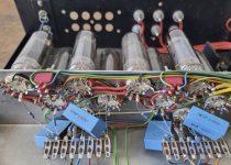
BTW here are pictures of another series 5 amp in the same case as mine - it's an integrated with some upgrades...
BTW here are pictures of another series 5 amp in the same case as mine - it's an integrated with some upgrades...
IMHO it is good and not to complicated in between the EL84 cathodes to add one 50R/5W wire-wound trim-pot to precise adjust OPS- DC symmetry and to lower the THD ,
also by raising value of R18 (3K3) to 3K9 or 4K7 OPS quiescent current can be lowered which can lead to EL84 cooler operation .
also by raising value of R18 (3K3) to 3K9 or 4K7 OPS quiescent current can be lowered which can lead to EL84 cooler operation .
Attachments
The EL84s are running pretty hot, the simulation shows 11.6W (12W datasheet max for the plate). I'd increase the negative bias a bit. Or go for Soviet 6P14P-EV or the modern reincarnations, they are specified for 14W max plate dissipation).

I'd go for self-bias, individual R/C for each EL84. A little bit less power, but not significant.
One with fixed bias, as in your schematic, one with self-bias.Great work! Can you please post the simulation file?
Attachments
Can you please show me how this would look like? I am not experienced with tubes...
Great work! Can you please post the simulation file?
Thanks, I will consider! Why did you mark the 22uF cap next to R18 with a red arrow?
The EL84s are running pretty hot, the simulation shows 11.6W (12W datasheet max for the plate). I'd increase the negative bias a bit. Or go for Soviet 6P14P-EV or the modern reincarnations, they are specified for 14W max plate dissipation).
Great work! Can you please post the simulation file?
IMHO it is good and not to complicated in between the EL84 cathodes to add one 50R/5W wire-wound trim-pot to precise adjust OPS- DC symmetry and to lower the THD ,
also by raising value of R18 (3K3) to 3K9 or 4K7 OPS quiescent current can be lowered which can lead to EL84 cooler operation .
Thanks, I will consider! Why did you mark the 22uF cap next to R18 with a red arrow?
Is not a good idea to out a pot, there is a mobile contact where is flowing around 60 mA
The only way to check and set the bias is as suggested
1 ohm for each cathode to ground and two pot for bias each channel
It is not an hard job even the soave is little
In this way you can also balance at the best the dc current in the trafo
Then a solution of autobuas is also a way but it is not my first choice
Because that 22uF original voltage rating is IMO almost on the edge (only 16V !) , since that cap is on the one very critical point for filtration of EL84 -g1 negative source supply than 25V or even more is way better and safer value , personally on that place I will insert 22uF/50V/105C quality cap ,Thanks, I will consider! Why did you mark the 22uF cap next to R18 with a red arrow?
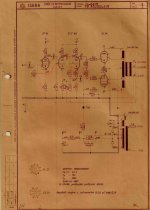
btw ,also check this Iskra HI-FI tube amp schematic ,where between two EL34 cathodes is inserted one 50R/4W W.W. trim pot to precise adjust DC offset .
Attachments
Last edited:
I'd go for self-bias, individual R/C for each EL84. A little bit less power, but not significant.
Thanks for the simulation files. I couldn't open them on my system yet, have to install libs etc first. For the R/C: are 100u caps with 63V rating fine? And for the cathode resistors: should I see them as protection fuses and use 1W/390R or even 0.65W rated resistors?

Last edited:
Because that 22uF original voltage rating is IMO almost on the edge (only 16V !) , since that cap is on the one very critical point for filtration of EL84 -g1 negative source supply than 25V or even more is way better and safer value , personally on that place I will insert 22uF/50V/105C quality cap ,
btw ,also check this Iskra HI-FI tube amp schematic ,where between two EL34 cathodes is inserted one 50R/4W W.W. trim pot to precise adjust DC offset .
Thanks!! Do I have to connect the wire wound trimmer between the parallel tubes likes this?

jpk73
Yes ! , just like that
,advantage of that solution is that negative bias source is very simple , no any trim pot for adjusting negative bias , which in case of fail can be catastrophic for OPS , in the vintage Iskra HI-FI amp that solution work very stable for decades , only what is needed is sometime to connect voltmeter in between the EL34 cathodes and to adjust for zero Volt , to emphasize that 50R/5W W.W. trim pot stays on the very low impedance points , so there is no risk of collecting any hum or noise.
- Home
- Amplifiers
- Tubes / Valves
- My Croft series 5 schematic