I typically use 220u or higher for cathode bypass. 63V is fine indeedFor the R/C: are 100u caps with 63V rating fine?
The dissipation for those resistors is ~0.4W, therefore 1W would be the minimum, better 2W. And use a proper fuse in B+, the EL84 is a relatively low power tube, does not make a lot of sense to use an individual fuse for each tube.And for the cathode resistors: should I see them as protection fuses and use 1W/390R or even 0.65W rated resistors?
by raising value of R18 (3K3) to 3K9 or 4K7 OPS quiescent current can be lowered which can lead to EL84 cooler operation .
I struggle to understand... May I ask to explain again: if I have R18=3K3 (and R17=1K) the output voltage of the voltage divider will be -13.8V, while with R18=3K9 I will get -14.3V: doesn't that mean I will have more (negative) voltage hence more quiescent current hence hotter output tubes...?
More negative = less bias currentwill have more (negative) voltage hence more quiescent current hence hotter output tubes...?
That works, but you need very well matched EL84s, due to all of them sharing the same cathode resistor. I'd really recommend individual cathode resistors and caps.
Nice find! I have never come across a Series 5 with horizontal valves, just the arrangement you see in the pair I owned.Hi,
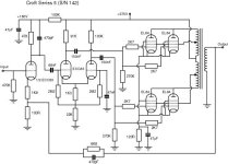
with your kind forum help I finally found a tube amp that I really like: a Croft series 5 with horizontal tubes inside a standard case and SS regulator. It's different from the one shown here (with that schematic). The mains lead was without PE connection, so I lifted GND from chassis through a 22R thermistor and connected PE to chassis. I replaced the 3 small lytics and am waiting for shippment of the 3 main smoothers to replace them as well. It sounds really fantastic! I am trying to figure out the schematic, but it's not so easy as I can't see some resistor color codes well. Please let me know if you think some values are off:
EDIT: just updated the schematic with R5=820k and other minor corrections
What do you mean by "PE"? As I state in my article, the lack of a safety earth connection for the Series 5 is a potentially lethal shortcoming. I never got around this, apart from never turning the amps on without them being connected to the preamp. In my case, the signal earth for both channels was connected to the chassis of the preamp and hence safety earth, but you shouldn't have to rely on this. Does your Series 5 have a three-core mains lead?
Alex
I saw your article and decided to do something after reading your article. Your articles are very helpful for me because I am also working on a super micro and an integrated phono. Many thanks!
My series 5 amp had a 3core lead but PE (protective earth) was not connected, and there was no schuko plug at the end of the cable (at first the yellow/green wire in the cable was cut so short that I thought it's only a 2wire lead). The RCAs were already isolated from chassis. I lifted GND through a 22R thermistor and connected PE to chassis as shown in my shematic. The amp should be safe now, right?
My series 5 amp had a 3core lead but PE (protective earth) was not connected, and there was no schuko plug at the end of the cable (at first the yellow/green wire in the cable was cut so short that I thought it's only a 2wire lead). The RCAs were already isolated from chassis. I lifted GND through a 22R thermistor and connected PE to chassis as shown in my shematic. The amp should be safe now, right?
Last edited:
Even though I sold both my Series 5s over five years ago they were a special amplifier. When the buyer came to pick them up I gave him a short demonstration, and though the EL84 valves were probably overdue for replacement I realised I had forgotten how good the amps sounded.
Alex
Alex
- Home
- Amplifiers
- Tubes / Valves
- My Croft series 5 schematic
