Hi. I'm starting this thread to present my own version of the Blue Hawaii Tube headphone amp. I'll post schematics, pcb layout and pictures. Feel free to comment on my schematics if I did obvious errors. The Power supply is completed, and tested ok. I'll proceed with the amp pcb design in the next few weeks. Thanks for reading.
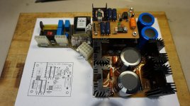
Here my own version of the power supply. It has to fit into a recycled enclosure that I had in stock, hence the custom pcb design.
The supply supports 115/230V main voltage selection. Has provision for the remote HV power transformer in/out leads, and the main 12 pins supply outputs connectors. It will connect to an AMP circular connector on the back.
Both end of the umbilical cable will use different connector pins pattern so it wont, be able to mix up the in and out. Also the 12 pins main pcb connector includes a 2 pins interlock that will be terminated into the main preamp enclosure. So the HV supply won't turn on unless the power supply and the preamp are actually connected. A small 2 pins jumper on the supply can be used to complete the interlock to test the supply.
The supply is more or less following the original published schematic. I modified the HV regulators to use IXYS 10M90S CCS chip instead of the original led/2SA1968 transistor (no longer in production) CCS to polarize the zener volt reference.
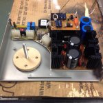
I was limited in space and I had to relocate the +/-15V regulators and the HV turn-on timer on a separate pcb that sits on top of the heater voltage transformer. The +/115 and the heater supplies turn on immediately, then after approx. 45 sec, the HV is turn on. Both +/-400V supplies are protected by fuses. Over rated resistors, zener diodes and heatsinks are used for the HV.
The 6.3Vac heater supply is referenced to the -400V supply to prevent exceeding the EL34 maximum Vh-k max of 100V. The Cathde will sit at around -350V, the the maximum Vh-k won't be exceeded.
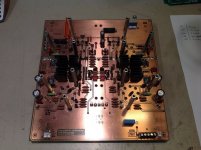
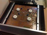
Finally received the HV transformer and completed the assembly. It is a nice fit, but there probably not a cubic cm of space left 😉
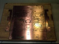
Here a picture of my supply pcb, schematic, PCB and final assembly
Here my own version of the power supply. It has to fit into a recycled enclosure that I had in stock, hence the custom pcb design.
The supply supports 115/230V main voltage selection. Has provision for the remote HV power transformer in/out leads, and the main 12 pins supply outputs connectors. It will connect to an AMP circular connector on the back.
Both end of the umbilical cable will use different connector pins pattern so it wont, be able to mix up the in and out. Also the 12 pins main pcb connector includes a 2 pins interlock that will be terminated into the main preamp enclosure. So the HV supply won't turn on unless the power supply and the preamp are actually connected. A small 2 pins jumper on the supply can be used to complete the interlock to test the supply.
The supply is more or less following the original published schematic. I modified the HV regulators to use IXYS 10M90S CCS chip instead of the original led/2SA1968 transistor (no longer in production) CCS to polarize the zener volt reference.
I was limited in space and I had to relocate the +/-15V regulators and the HV turn-on timer on a separate pcb that sits on top of the heater voltage transformer. The +/115 and the heater supplies turn on immediately, then after approx. 45 sec, the HV is turn on. Both +/-400V supplies are protected by fuses. Over rated resistors, zener diodes and heatsinks are used for the HV.
The 6.3Vac heater supply is referenced to the -400V supply to prevent exceeding the EL34 maximum Vh-k max of 100V. The Cathde will sit at around -350V, the the maximum Vh-k won't be exceeded.
Finally received the HV transformer and completed the assembly. It is a nice fit, but there probably not a cubic cm of space left 😉
Here a picture of my supply pcb, schematic, PCB and final assembly
Attachments
Last edited:
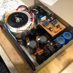
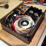
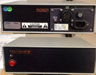
Here the final power supply schematic and the complete power supply, tested and ready to roll 😀.
I had to install a wood plate under the toroid to lift it so it doesn't touch the stud already in the enclosure. It also gives me some free space to run the toroid wires.
Already started on the amp PCB design.
I had to install a wood plate under the toroid to lift it so it doesn't touch the stud already in the enclosure. It also gives me some free space to run the toroid wires.
Already started on the amp PCB design.
Attachments
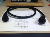
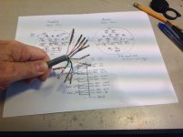
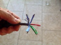
Umbilical cable, 4FT is completed. I used Belden 8778 cable, 6 pairs twisted & individually shielded, tinned copper 22AWG wire covered with braided protection sleeve. It is terminated with matching AMP circular connectors and gold pins. Supply and amp connectors don't have the same pin pattern, so they cannot be mix up...
The pair shields are all tied together at the amp side only, and will be connected to signal gnd inside the amp. Naturally I used one of the twisted pair to carry the filament 6.3Vac voltage...
As mentioned previously two wires are used as interlink for the HV power-on, as a protection. They will be shorted together on the amp connector. Hence the HV won't be activated unless the cable is correctly connected at both ends.
Attachments
Thanks. It will be built around the HiFi2000 enclosure ''Mini Dissipante 2U 250mm 10mm SILVER front panel - 2mm aluminum covers and 3mm rear panel'', part Number 1MNPDA02/33/250B.
Also I'll have a fancy volume control that I have in stock since a long time, TKD 2P65CS, like this one: TKD 2P65CS - $180.
My own version will be Single ended only for now, but the main PCB will support balance operation. If I ever have the need to go balanced, I'll just need to add a balance volume control, and a pair of XLR connectors at the back...
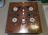
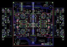
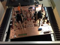
Progress. Completed the main PCB, based on the original Blue Hawaii BHSE pictures I saw and Kevin Gilmore original PCB layout. Left & Right mirror image layout, long standoff to install the PCB facing down into the enclosure, with the tube sockets, CCS leds and adjustment trimmer accessible from the top.
I'll have custom small pcb on each heatsink to mount the tube CCS and 2SC3675 power transistor.
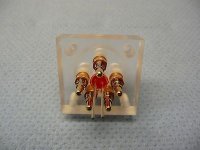
RN60D Vishay film resistors, space for large 10uF HV film capacitors (recycled), Chassis/GND lift network, all power resistors are mounted 'in the air' over the PCB, that has ventilation holes in it, small J79/K216 heatsinks have also pcb ventilation holes, integral ground plane. I have Heater and HV power-on leds, and a custom transparent STAX connector with central illumination led.
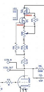
The tube CCS uses modern 10M90S/DN2540 combo adjustable to 25ma, as the original.
I'll have custom small pcb on each heatsink to mount the tube CCS and 2SC3675 power transistor.
RN60D Vishay film resistors, space for large 10uF HV film capacitors (recycled), Chassis/GND lift network, all power resistors are mounted 'in the air' over the PCB, that has ventilation holes in it, small J79/K216 heatsinks have also pcb ventilation holes, integral ground plane. I have Heater and HV power-on leds, and a custom transparent STAX connector with central illumination led.
The tube CCS uses modern 10M90S/DN2540 combo adjustable to 25ma, as the original.
Attachments
Last edited:
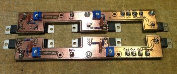
Here both CCS small PCB, tested and adjusted to 25ma. The trimmer gives me a range of 3ma to 29ma.
I included the typical 10M90S/DN2540 CCS I used. The only difference is the trimmer series resistors is 56R instead of the schematic 200R. And don't forget this is just a typical schematic, not the Blue Hawaii...
Still no decided if I'll use some plate resistor. Some reported that they prefer the sound of a small plate resistor. It will be easy to try, the CCS Output connects to the main pcb by wire. I'll have simplt to replace the wire by the test resistor.
Attachments
Last edited:
Umbilical cable, 4FT is completed. I used Belden 8778 cable, 6 pairs twisted & individually shielded, tinned copper 22AWG wire covered with braided protection sleeve. It is terminated with matching AMP circular connectors and gold pins. Supply and amp connectors don't have the same pin pattern, so they cannot be mix up...
The pair shields are all tied together at the amp side only, and will be connected to signal gnd inside the amp. Naturally I used one of the twisted pair to carry the filament 6.3Vac voltage...
As mentioned previously two wires are used as interlink for the HV power-on, as a protection. They will be shorted together on the amp connector. Hence the HV won't be activated unless the cable is correctly connected at both ends.
Isn't that is a very, very expensive cable?
When looking at the Mouser website.
I think you're looking at the price for a 100ft spool of that cable.
I'd be more worried about the voltage rating.
It's an incredible build though! Congratulations!
I'd be more worried about the voltage rating.
It's an incredible build though! Congratulations!
I think you're looking at the price for a 100ft spool of that cable.
I'd be more worried about the voltage rating.
It's an incredible build though! Congratulations!
Yes, I did but there was no possiblilty for ordering say a few meters. Or did I overlook something?
I'd be more worried about the voltage rating.
22 AWG wire should be fine up to 6.3 Amp.
- Home
- Amplifiers
- Headphone Systems
- My Blue Hawaii Tube Amplifier version