Hi Russ and Brian (and Mauro, of course)
A similar question was asked at the "Kooka" thread.
¿How high In capacity can we go to replace the Panasonic FC's decoupling caps? (not C9) Whithout jeopardizing performance, that is.
I've seen some "cheap" Rubicon's ZL 560uF/50V on the market place 😉
Cheers
Mauricio
A similar question was asked at the "Kooka" thread.
¿How high In capacity can we go to replace the Panasonic FC's decoupling caps? (not C9) Whithout jeopardizing performance, that is.
I've seen some "cheap" Rubicon's ZL 560uF/50V on the market place 😉
Cheers
Mauricio
maxlorenz said:¿How high In capacity can we go to replace the Panasonic FC's decoupling caps? (not C9) Whithout jeopardizing performance, that is.
The most important factor there is ESR. if the cap you are replacing the 220uf FCs with has as low an ESR value or lower it will work just fine. 🙂
The most important factor there is ESR. if the cap you are replacing the 220uf FCs with has as low an ESR value or lower it will work just fine.
OK.
Thanks!
M
yet another 3886 RefC finished
Hi,
yesterday I have finished my RefC Mono-Amps. First of all I have to thank Mauro for his circuit and Russ+Brian for excellent PCB-design and the Ref-C kit.
It was late in the evening when I finshed the Mono-Amps, so had not time for long listening. First impression was a very soft sound, good soundstage and focus. I will do some more listening tests tomorrow.
I have used the TwistedPair Kit as a starting point and replaced some parts (e.g. Mica instead of foils, Vishay Dale resistors, Rubycon ZA, 0,47 Ohm Film Resistor, Black Gates, MKP-Bypasses). The transformer is a 200 VA type.
Arne
Attachments
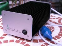

 GREAT ! Where did you get the cases and frontplates ?
Trafos look quite small; how many VA ?
However - fancy work !
Hi,
the trafos are 200 VA types. They are already custom-made products. Normal 200 VA transformer have diameter > 105 mm, which would not fit in the small cases.
The frontplates are from Schaeffer-Apparatebau (http://www.frontpanelexpress.com/ in US).
The heatsinks profiles are from http://www.fischerelektronik.de/.
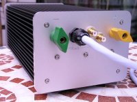
Attached you will find a close up of the frontplate.
Arne
the trafos are 200 VA types. They are already custom-made products. Normal 200 VA transformer have diameter > 105 mm, which would not fit in the small cases.
The frontplates are from Schaeffer-Apparatebau (http://www.frontpanelexpress.com/ in US).
The heatsinks profiles are from http://www.fischerelektronik.de/.
Attached you will find a close up of the frontplate.
Arne
Attachments

Very nice!
Excellent work, clean wiring and pretty units. Two hopefully constructives.
Why the two RCA input jacks?
Also, your input power cord is very close to the input section. This could give a little hum. With the high impedance of the input ithe hum level rejection can be an issue. If you get any hum it may come from this.
George
THX!
The second input jack is for later purposes. If I am fully satisfied with the sound of the RefC I will use them to activate my manger speakers. The crossover for the manger driver will be a 4,7nF capacitor (+100K input impedance) which will fit easy in the Amp-Case.
The power cord wire I am using is a shielded one. During listening tests yesterday I could not detect any hum or high-frequency noise. Because of little space for the connectors on the backplate I was not able to arrange them in a better way.
Arne
Arne,
Great work there mate! that is a real work of art. The 200VA trafo should be plenty for each monobloc. I love the compact case. It is exactly what I had envisioned. The font panel is amazing!!! Simple but elegant. I love the twisted pear, very cool, and giving Mauro credit right on the front panel is a very classy move. Good work.
I hope you get a chance to put it through its paces soon. Your setup seems very solid and well planned. I think you will be rewarded for your extra work. Enjoy the fruit of your labor.
Thanks so much for the kind words. 😎
Cheers!
Russ
Great work there mate!
that is a real work of art. The 200VA trafo should be plenty for each monobloc. I love the compact case. It is exactly what I had envisioned. The font panel is amazing!!! Simple but elegant. I love the twisted pear, very cool, and giving Mauro credit right on the front panel is a very classy move. Good work.I hope you get a chance to put it through its paces soon. Your setup seems very solid and well planned. I think you will be rewarded for your extra work. Enjoy the fruit of your labor.
Thanks so much for the kind words. 😎
Cheers!
Russ
Another pair of RevCs
... and another one:
I made these for a fellow hifi enthusiast, he wanted as much wood as possible, so I made those boxes of birch plywood and birch veneer. The heatsinks are handmilled out of stock ones, it was a pain to do.
Front view of both:
Top view:
The innards, upper level ...
...and ground floor.
Not shown is a tinplate shielding between the levels as well as the stainless steal tissue coating on the inner wall of the boxes. It´s to been seen in the cutouts in the top view.
I´ve built sereval RevCs in the past, with these I tried enhancing the psu capacitance to 24700 µF with and without bypassing and snubbers. Whatever I did, nothing changed to better results. Sound went fat and upper mids were washed out somehow. So I returned to the original configuration.
Hope this gives a suggestion. Greetings to Russ and Brian !
P.S.: Brian, in these RevCs I tried the Pana FM feedback caps, they are really nice ! Will order another kit soon ...
... and another one:
An externally hosted image should be here but it was not working when we last tested it.
I made these for a fellow hifi enthusiast, he wanted as much wood as possible, so I made those boxes of birch plywood and birch veneer. The heatsinks are handmilled out of stock ones, it was a pain to do.
Front view of both:
An externally hosted image should be here but it was not working when we last tested it.
Top view:
An externally hosted image should be here but it was not working when we last tested it.
The innards, upper level ...
An externally hosted image should be here but it was not working when we last tested it.
...and ground floor.
An externally hosted image should be here but it was not working when we last tested it.
Not shown is a tinplate shielding between the levels as well as the stainless steal tissue coating on the inner wall of the boxes. It´s to been seen in the cutouts in the top view.
I´ve built sereval RevCs in the past, with these I tried enhancing the psu capacitance to 24700 µF with and without bypassing and snubbers. Whatever I did, nothing changed to better results. Sound went fat and upper mids were washed out somehow. So I returned to the original configuration.
Hope this gives a suggestion. Greetings to Russ and Brian !
P.S.: Brian, in these RevCs I tried the Pana FM feedback caps, they are really nice ! Will order another kit soon ...
All these nice cases are great to see!
Great! They are standard in the kits now for C9.
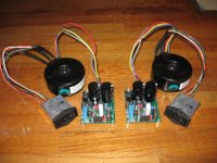
Also, I noticed you have you input caps mounted on the RCA jack rather than on the board. Are these the kit caps?
P.S.: Brian, in these RevCs I tried the Pana FM feedback caps, they are really nice ! Will order another kit soon ...
Great! They are standard in the kits now for C9.
Also, I noticed you have you input caps mounted on the RCA jack rather than on the board. Are these the kit caps?
No they´re not. They are also WIMA MKP 10 1.0 µF, but some years old and been used in other amps. Somehow I feel they sound the better the longer they´re in use. The mounting is because I tried various input caps caps with this setup, including this russian teflon stuff and Mundorf MCap ZN. For my taste nothing beats those Wimas.
Project under construction
While not done with my RevC, I am much farther along that when I first discovered this thread a few months ago. So far, I have the RevC boards completed with the upgraded diodes, 300VA Plitron transformers, Qualtek power entry modules, and Vampire BFP posts. On order are a couple of Lansing B-type grey box enclosures (2u tall, half width, 8 inches deep). I still need to specify my RCA input connectors and the heatsinks. My plan is to mount the heatsinks outside the enclosures on the back. Perhaps 3 inches square--suggestions for heatsinks welcome. Thanks for viewing.
While not done with my RevC, I am much farther along that when I first discovered this thread a few months ago. So far, I have the RevC boards completed with the upgraded diodes, 300VA Plitron transformers, Qualtek power entry modules, and Vampire BFP posts. On order are a couple of Lansing B-type grey box enclosures (2u tall, half width, 8 inches deep). I still need to specify my RCA input connectors and the heatsinks. My plan is to mount the heatsinks outside the enclosures on the back. Perhaps 3 inches square--suggestions for heatsinks welcome. Thanks for viewing.
Attachments
Enclosure
I think you said 2 inches tall for the box. The Rev C will require more clearance for the 10K filter caps. I think the caps are about 2 inches tall, with a little breathing room under the board it is tight in a 3" tall box.
My power demand is real low, so I have gotten by without a real heatsink. Used an aluminum plate inside and just the cast aluminum box to radiate heat. With an additional aluminum plate the total thickness is maybe 3/16" over 3 - 4 square inches. Several hours playing only gets it a little warm right over the chips.
Good luck in getting yours playing.
George
Thanks for the prompt feedback. I am encouraged to hear that the chips don't get too warm. The Lansing Grey Boxes are sold by unit height, so 2u=3.5inches tall (should be plenty of room). I'll post pictures of the empty enclosures when I get them, and probably ask for opinions on layout.
I have 3" and 4" sections of the BarredBoss (ebay) heatsink available if you are interested. They are 5-3/8" wide. I use one 3" for each channel. One 4" would be fine for a pair as well, unless you are really beating on it.
Thoughts on amp layout
I would like some feedback on my RevC monoblock amps layout. The parts will be installed in identical Lansing B-style anodized aluminum Grey Boxes. The boxes are roughly 8" square and 3.5" tall each. This gives me some flexibility on layout. Here are some ideas on where to put the components. What do you think of these layouts? Any suggestions on which one or even something better?
Thanks.
Idea 1
Idea 2
Idea 3
I would like some feedback on my RevC monoblock amps layout. The parts will be installed in identical Lansing B-style anodized aluminum Grey Boxes. The boxes are roughly 8" square and 3.5" tall each. This gives me some flexibility on layout. Here are some ideas on where to put the components. What do you think of these layouts? Any suggestions on which one or even something better?
Thanks.
Idea 1
An externally hosted image should be here but it was not working when we last tested it.
Idea 2
An externally hosted image should be here but it was not working when we last tested it.
Idea 3
An externally hosted image should be here but it was not working when we last tested it.
This is what works for me
Either of those three layouts work be fine, even the internal heatsink if the case is ventilated enough. Depending on your power and current needs the chassis you are using may be fine. All the My_Ref's I have built have used the chassis alone to radiate the heat. Here is pic of the latest mono version.
Both channels are in the same Deltron box. The cast aluminum chassis are 30.00 each from Mouser if I remember right.
In another amp usin the stereo boards more aluminum plate was stacked to help transfer heat from the LM3886. Measuring the chip temp on both shows a single plate transfers as well as a thicker section.
I think keeping the transformer away from the input section is about all you need to worry about. The high impdeance (100K) will allow it to pick up a little hum if the fields are strong enough.
With good layout the amp should be very quiet. Even the ratsnest in the picture is dead quiet on 100 dB efficient speakers.
George
- Home
- Amplifiers
- Chip Amps
- My "audiophile" LM3886 approach