maf_au said:Hi Mauro,
I was wondering out aloud if the revC runs the resistors as warm as the revA.
If so, stacking the boards close together may be an issue for heat.
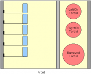
Something like my poor drawing attached... 🙂
Michael
Hi Michael,
The only thing that would possibly run hotter/cooler betwen the different revisions is the LM338/LM3886 combo itself. All of the power resistors disipate a nearly constant current no matter what.
I would think(though I have never tried )you should be able to stack, as long as you provide ample ventilation above and below your stack, and give the PCBs at least 20mm or so between eachother. The heatnk will need to be big, and vertically oriented fins would be best. You could alway force air in from below by placing a fan at the top of the bottom.
I don't know if I would stack myself, I would more likely orient the PCB vertically(on its side). Which would allow you to put for or so easily on one side. That should work fine, and may even have some thermal advantages. That is how I plan to do my 7 channel amp.
Cheers!
Russ
Cheers!
Russ
The one thing I would be worried about though is that, to my mind, the top most chip would be recieving conducted heat from all chips below it. Am I wrong?
I am interested to hear all your views on this as I am building the Leach amp ATM and with the layout - it is impossible not to have one set of transistors being more heated than another. The layout is described in ASCII below
------------X---X---X--
|
|
|
------------Y---Y---Y--
I am interested to hear all your views on this as I am building the Leach amp ATM and with the layout - it is impossible not to have one set of transistors being more heated than another. The layout is described in ASCII below
------------X---X---X--
|
|
|
------------Y---Y---Y--
Russ White said:
I don't know if I would stack myself, I would more likely orient the PCB vertically(on its side). Which would allow you to put for or so easily on one side. That should work fine, and may even have some thermal advantages. That is how I plan to do my 7 channel amp.
Hi Russ,
If you have a look at my second drawing, I think you have described what I have drawn. It's a stack laid over on it's side. Maybe it's not clear (it's a plan, not an elevation)... Anyway, you think the heat radiating from the resistors won't cause the amp too much heat stress?
Byrd,
Yes, the top transistor will cop the heat soaking up from those below it, but with the monoblock (on it's side) configuration, That's not the issue as there is no circuit above another.
Sounds like, with good ventilation the heat shouldn't be too bad.
Michael
maf_au said:
If you have a look at my second drawing, I think you have described what I have drawn. It's a stack laid over on it's side. Maybe it's not clear (it's a plan, not an elevation)... Anyway, you think the heat radiating from the resistors won't cause the amp too much heat stress?
Michael
Sorry I missed your second pic. Yep, Thats close to what I had in mind. The heat from the resistors is not really that significant in the grand scheme of things. Just put a few ventilation holes above and below each PCB so that the holes are pretty much dirctly above the power resistors.
The power resistor are disspating less than 1W apiece, and when you tacke into consideration that the chips and trafos will be dissapting orders of magitude more power it is just a drop in the bucket. 🙂 But certainly something you must remember.
Cheers!
Russ
Betas Running
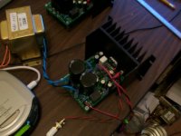
The Betas are up and running. Only made enough breadboard to test one at a time, but both check out. 3.0 mV so seem real clean. First impression with only one channel at a time is that the brightness at the top end is smoothed out a bit.
Will try to get both running together later this evening.
The Betas are up and running. Only made enough breadboard to test one at a time, but both check out. 3.0 mV so seem real clean. First impression with only one channel at a time is that the brightness at the top end is smoothed out a bit.
Will try to get both running together later this evening.
Attachments
another amp arrives
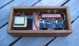
Just wanted to add my amp to the list of completed amps built using the original boards that Mauro, Russ, and Brian put together. The only change I made from the parts provided by Brian is to change the 220uf feedback electrolytic to a Panasonic FC and bypass it with .1uf and 0.01uf film caps.
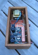
I built it using the now lamented Parts Express $7 special and put it in a homemade oak box. I built an internal copper ground plane / shield using copper circuit board stock and just used a chunk of copper (1" x 4" x 6") as the heatsink.
After playing for an hour or so the heat sink gets warm to the touch but not so hot that you can't leave your finger there. There are ventilation holes next to the copper block, so I assume theres a decent chimney effect helping to keep the temperature in control.
I normally invoke a 24 hour rule before seriously commenting on the sound quality but I will say early indications are promising. One trick that I've found with other amps seems to be true here - the polarity of the transformer makes a difference. Try swapping the leads going to the board and you'll see that one way sounds better.
Among the changes I'm considering are better input caps (I've got some nice Russian military surplus oil caps) and fast/soft recovery diodes.
I'll attach a few photos for those interested.
Thanks,
---Gary
Just wanted to add my amp to the list of completed amps built using the original boards that Mauro, Russ, and Brian put together. The only change I made from the parts provided by Brian is to change the 220uf feedback electrolytic to a Panasonic FC and bypass it with .1uf and 0.01uf film caps.
I built it using the now lamented Parts Express $7 special and put it in a homemade oak box. I built an internal copper ground plane / shield using copper circuit board stock and just used a chunk of copper (1" x 4" x 6") as the heatsink.
After playing for an hour or so the heat sink gets warm to the touch but not so hot that you can't leave your finger there. There are ventilation holes next to the copper block, so I assume theres a decent chimney effect helping to keep the temperature in control.
I normally invoke a 24 hour rule before seriously commenting on the sound quality but I will say early indications are promising. One trick that I've found with other amps seems to be true here - the polarity of the transformer makes a difference. Try swapping the leads going to the board and you'll see that one way sounds better.
Among the changes I'm considering are better input caps (I've got some nice Russian military surplus oil caps) and fast/soft recovery diodes.
I'll attach a few photos for those interested.
Thanks,
---Gary
Attachments

Very nice Gary!
I like wood cases.
Please give us some more in depth listening impressions when you have a chance. 😀
Great work.
Cheers!
Russ
I like wood cases.
Please give us some more in depth listening impressions when you have a chance. 😀
Great work.
Cheers!
Russ
Hey
I have just build this amp on the rev. C Monoboards, but i'm having trouble with one of the boards. I measure about 80mV DC on the output. Changing the Opamp helps for a wile, but the DC is slowly rising after some use. Does anyone know what may cause this?
Tanx for any replies
Stephen
I have just build this amp on the rev. C Monoboards, but i'm having trouble with one of the boards. I measure about 80mV DC on the output. Changing the Opamp helps for a wile, but the DC is slowly rising after some use. Does anyone know what may cause this?
Tanx for any replies
Stephen
Check this
Measure your voltage on the metal tab of the LM3886. First amp I built only measured about -26 volts, the other channel was -34. I could never find the issue, built another board just to be safe. The offending channel had high offset.
Later I noticed that a + rail cap on one channel and a - rail cap on the other was ballooning the top of the cap. These were the 220 ufd 50 volt ones. Stipped the board, it looked like it was close to going kapop. But only the 1K resistors got hot. Supect a damaged LM3886. The measured voltages were fine, +/- 34 volt dc. Even the low reading lm3886 never heated up.
There is a lot I do not know about these chips, the pair of LM3886T had been in my closet for about 2 years. Might have gotten crunched somehow.
George
stephenm said:Hey
I have just build this amp on the rev. C Monoboards, but i'm having trouble with one of the boards. I measure about 80mV DC on the output. Changing the Opamp helps for a wile, but the DC is slowly rising after some use. Does anyone know what may cause this?
Tanx for any replies
Stephen
Measure your voltage on the metal tab of the LM3886. First amp I built only measured about -26 volts, the other channel was -34. I could never find the issue, built another board just to be safe. The offending channel had high offset.
Later I noticed that a + rail cap on one channel and a - rail cap on the other was ballooning the top of the cap. These were the 220 ufd 50 volt ones. Stipped the board, it looked like it was close to going kapop. But only the 1K resistors got hot. Supect a damaged LM3886. The measured voltages were fine, +/- 34 volt dc. Even the low reading lm3886 never heated up.
There is a lot I do not know about these chips, the pair of LM3886T had been in my closet for about 2 years. Might have gotten crunched somehow.
George
Re: Betas Running
I have several (10-12) of those exact heat sinks...
hayenc said:The Betas are up and running. Only made enough breadboard to test one at a time, but both check out. 3.0 mV so seem real clean. First impression with only one channel at a time is that the brightness at the top end is smoothed out a bit.
Will try to get both running together later this evening.
I have several (10-12) of those exact heat sinks...
Yes, I got a bunch of the heat sinks for around a buck each on eBay. From what I could find on documentation, they seem to be about 1.8 which is what the National Semi design guide shows for the 3886 at 35 volts. They are warm but not hot.
Transformer is also warm, but not hot driving both channels now.
Transformer is also warm, but not hot driving both channels now.
why does it get so warm?
I'm wondering what about the original My_Ref (aka Rev A) causes the LM3886 to generate so much heat. I've built a pretty standard LM3875 based gainclone with exactly the same heat sink and it barely gets warm to the touch.
My new Rev A amplifier gets quite hot to the touch - not dangerously so, but something must be causing it to generate so much heat. I checked the output on my 20Mhz scope and couldn't see any oscillations when idling but I'm wondering if things might be marginally stable. I'm going to convert it to a Rev C and see what that does to the heat generation.
Any insight from the gang here? I seem to recall that Russ also complained about the heat and things seemed to get better with his Rev C amps.
Thanks,
---Gary
Re: why does it get so warm?
The one area here I see is the 22K and 47K resistor pairs. If you used 1% instead of 0.1% there will be a lot more heat generated by the LM3886.
My Rev A barely heats the chip. At idle, most of the heat seems to be coming off the dropping resistors, not the LM3886.
Playing music heats it a little, but mine is heatsinked to the small box. It does not have a real heatsink and plays for hours with areas of the box maybe getting in the 120 - 130 degree range. The area behind the chips is no warmer than the metal around the vents.
George
GaryB said:I'm wondering what about the original My_Ref (aka Rev A) causes the LM3886 to generate so much heat. I've built a pretty standard LM3875 based gainclone with exactly the same heat sink and it barely gets warm to the touch.
My new Rev A amplifier gets quite hot to the touch - not dangerously so, but something must be causing it to generate so much heat. I checked the output on my 20Mhz scope and couldn't see any oscillations when idling but I'm wondering if things might be marginally stable. I'm going to convert it to a Rev C and see what that does to the heat generation.
Any insight from the gang here? I seem to recall that Russ also complained about the heat and things seemed to get better with his Rev C amps.
Thanks,
---Gary
The one area here I see is the 22K and 47K resistor pairs. If you used 1% instead of 0.1% there will be a lot more heat generated by the LM3886.
My Rev A barely heats the chip. At idle, most of the heat seems to be coming off the dropping resistors, not the LM3886.
Playing music heats it a little, but mine is heatsinked to the small box. It does not have a real heatsink and plays for hours with areas of the box maybe getting in the 120 - 130 degree range. The area behind the chips is no warmer than the metal around the vents.
George
Hi all,
Doesn't exist any thermal variation among the revA and RevC.
To parity of PSvcc (+-35Vdc), without signal, the temperature is identical in that of LM3886 GC.
During the operation, My_Ref uses about 15 % more power of GC (8ohm load), on account of the energy losses on res. 0.47ohm and of the "current pump" configuration .
The 1K 2W res are about 50°C. If the card is closed in a box, with little air exchange, Tamb becomes about 40°C, and Theatsink = Theatsink+Tamb= about 50-60°C.
At least this it happens on my prototypes.
I don't know other problems caused by components or constructions distinct from mine, but the indications of Russ and Brian on revA has not given me signs of particular problems...
Ciao
Mauro
I agree with Mauro. No significant difference in heat between rev A or the C monoblocks. I get more heat when the music is cranked up with a lot of bass, or when I am driving the 4 ohm MTM speakers, but idle neither gets very warm.
There is only one small difference that I have been able to measure. The idle curent draw of REV A is a little higher than my REV C monoblocs. The only reason I can come up with, and I expect Mauro to please correct me if I am wrong, is that the REV C circuit utilizes the offset null pin of the LM318, which reduces offset to virtually zero. This means the LM3886 and LM318 have to do less work to keep the circuit in balance(stable).
Cheers!
Russ
Cheers!
Russ
- Home
- Amplifiers
- Chip Amps
- My "audiophile" LM3886 approach