To varun21,
Some versions of MyRef use pin 8 on the LM318n. Check your pcb if pin 8 is connected. TL071 pin 8 = nc
Some versions of MyRef use pin 8 on the LM318n. Check your pcb if pin 8 is connected. TL071 pin 8 = nc
measure the output offset from the speaker output terminal to the main audio ground on the PCB.
If the relay is triggered to OFF the speaker return is isolated and you can't use it to reference to the zero volts.
If the relay is triggered to OFF the speaker return is isolated and you can't use it to reference to the zero volts.
@mark: Yes pin 8 is connected to the PCB and goes to R39 and R43. So apparently TL071c works without compensation while LM318n is either faulty or needs some custom compensation? (Pls note: I'm using TL071-"C" if that matters.)
@andrew: I do all my measurements from the power ground (0v rail). With TL071c it works and gives .005v.
I've got some new LM318n s and I'm planning to plug them into the socket. Should I go ahead?
@andrew: I do all my measurements from the power ground (0v rail). With TL071c it works and gives .005v.
I've got some new LM318n s and I'm planning to plug them into the socket. Should I go ahead?
Finally plugged in LM381n and yes it did have some stability issue. Sometimes it click in and I can play. But at other times I switch on and it comes on for a fraction of a sec and then goes off (relay). When it works it does have a HF oscillation (something 13-14KHz and above).
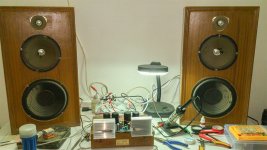
But I'm so glad I was pleasantly surprised by my DIY make-shift speakers living up to myref. I always thought my 3-way speakers would just sound dull without the tone controls of ESP project 97. Plugged in the TL071c again and I just sat right in the middle of the two for several hours and played out all my favs. The myref has a very clear, detailed image and sounds just like inside a movie hall or better. I feel as if I'm out there in the live.
The paint on the enclosure will dry by tomorrow and then once inside, the shield of the enclosure will hopefully reduce or rectify the oscillation of the myref.
From the looks of it, these look trash and those are some of the cheapest drivers I bought with my pocket money 15yrs back. But for now, my new 2-way speaker project is on indefinite hold.

So I turned it off and went for a break. When I returned, I switched on the mains with shivering hands (it's biting cold here). And I saw a spark on the PCB. The only switch I have currently is the AC mains. And then no sound. The relay clicks in though.
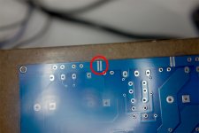
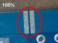
Upon microscopic inspection I saw that the PCB has some kind of a fuse built-in. Is it ok to jump it and try again?
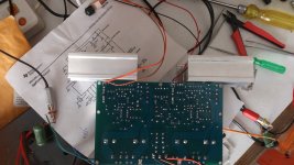
Photos from a blank PCB (I have 4 extras). Click for larger version.


Upon microscopic inspection I saw that the PCB has some kind of a fuse built-in. Is it ok to jump it and try again?
Photos from a blank PCB (I have 4 extras). Click for larger version.


Thanks AndrewT.
I jumped the breaks with solder. I put in the bulb tester and turned it on. The LED came on and the relay clicked.
If I remember correctly: I measured 0V at speaker gnd terminals (well the positive rail read 25.6VDC from there so they were not disconnected, suggesting that the relay was engaged). But this is if I remember correctly.
And no sound. Speakers felt dead.
I'm supplying 19VAC and getting 25.6VDC on the rails. I'm also using a TL071c instead of LM318 (they were blown and I'll only put in new ones once I've put this in it's enclosure).
The only way to turn on this thing now is to touch the Pin 1 of TL071c with a screwdriver etc. That somehow seems to engages the relay and turn on the speakers? This is contradictory to my measuring 0VDC on speaker gnd terminals.
What else should I try?
Thats not a fuse. You can change the fuction of the pcb. If it worked without then they probely need to be left as is. Are you still using shunts on your supply? This is not the way to get a stable supply. As the current increases the voltage decreases (Relais on relais off relais on.......). I think this amp needs 24Vac if only for the relais (30Vdc).
Hi Mark,
I bought 4 PCBs and one assembled piece from a chinese vendor. I saw a spark while turning it on (it played fine for hours earlier), and then I verified with my multimeter that the spark-gap fuse was in fact blown. When soldered it came right on but I'm using a blulb tester in series now. And apparently now it's too low a voltage. I'm planning to raise it to 22VAC and the primary in series with a 100W bulb. I'm currently connecting 4 ohm speakers.
My broken PCB had that gap/fuse blown (looked just like a shorted blown out metal). On the new pcb that was a 0 ohm, conducting joint.
thedeath0212: You should be able to use it provided it is actually a 24 - 0 - 24 and NOT a 24 - 0.
Sorry for the bad info. But if the voltages are not sufficient the Relais will not switch on and stay on.
Hi Mark,
Now worries. I couldn't troubleshoot this gem were it not for you guys.
Also my voltage was 19VAC with the bulb tester. Without it, the relay clicked right in.
One of the challenges I'm now facing is how to hook up the LM1036 tone control with myref. The challenge is actually the audio ground. I have a common ground for LM1036 and myref. Should I ignore the audio ground of the myref? Because if I use the AGND of myref as a audio input reference then the LM1036 outputs a voltage-hum (since the audio input is no longer references to its 0V gnd). Not sure if this post belongs to this thread though.
Hi,i have a subwoofer , I want a circuit using 2 LM3886, please share with me. Tks
This would not be the circuit you want for that.
Search for a PA100 (easiest), BA100 (harder) or BPA200 (hardest) circuit instead.
Hi Varune21,
You need to post new photo's. Probably a ground loop.
I wouldn't have a tone control but that's just me.
You need to post new photo's. Probably a ground loop.
I wouldn't have a tone control but that's just me.
This shows that the relay drive circuit is susceptable to supply voltage variations...........Also my voltage was 19VAC with the bulb tester. Without it, the relay clicked right in............
Correct 🙂
So far all is well. However I just replaced the TL071A with a LM318n from texas instruments (Chinese supplier on ebay). I get a hiss/HF oscillation. This is 12KHz and above. LM3886s run pretty warm. I shorted the audio inputs and the hiss fainted but is still audible. LM3886s stay warm/hot.
Currently the lead is 11" before it is shorted at the socket/end.
1. What could be the issue?
2. Will putting this in a case help?

Thanks.
So far all is well. However I just replaced the TL071A with a LM318n from texas instruments (Chinese supplier on ebay). I get a hiss/HF oscillation. This is 12KHz and above. LM3886s run pretty warm. I shorted the audio inputs and the hiss fainted but is still audible. LM3886s stay warm/hot.
Currently the lead is 11" before it is shorted at the socket/end.
1. What could be the issue?
2. Will putting this in a case help?

Thanks.
Last edited:
Hi Mark,
The hum wasn't a ground loop per se but was actually because the input signal had an audio ground separate from the 0V in myref. So basically I had to separate the 0V of LM1036 and the myref and link their audio grounds instead of connecting the 0V rails. (More specifically, myref was amplifying the difference between the ground and audio-grounds in addition to the signal, thus the hum).
The hiss/HF-oscillation with LM318n remains. Also, what kind of offset should I be measuring on the speaker terminals. Is it AC or DC?
Output offset is DC. Set your DMM to 199.9mVdc
Noise and hum and buzz is AC. Set your DMM to 199.9mVac
Noise and hum and buzz is AC. Set your DMM to 199.9mVac
AndrewT: Which offset matters? I guess AC will always be there as long as a signal is there. I guess it's the DC that's kills?
Also I guess could the HF oscillations/hiss be because of the forward feed 22pf on the LM318n (output to the non-inverting input)?
Also I guess could the HF oscillations/hiss be because of the forward feed 22pf on the LM318n (output to the non-inverting input)?
- Home
- Amplifiers
- Chip Amps
- My "audiophile" LM3886 approach