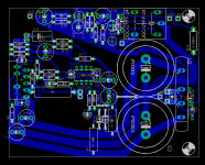
Russ White said:I changed the ground for the speaker protection circuit to run more directly to the star point.. 🙂
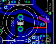
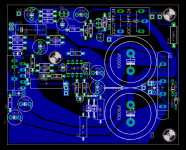
Hey Russ, Is there any reason why the track marked in red in the crop below has to be thinned and run around the corner like it does? Why not connect it as per the purple line I have scrawled across your beautiful artwork? 🙂
(I'm a newb, so feel free to enlighten me 🙂
Michael
Attachments
Russ White said:I changed the ground for the speaker protection circuit to run more directly to the star point.. 🙂
maf_au said:
Hey Russ, Is there any reason why the track marked in red in the crop below has to be thinned and run around the corner like it does? Why not connect it as per the purple line I have scrawled across your beautiful artwork? 🙂
(I'm a newb, so feel free to enlighten me 🙂
Michael
I did it that way because the two circuits should have different ground zones, so I made the trace for the protection circuit itself terminate as close to the center of the two power caps as possible.
I am not sure if that is necessary or not, but I thought it more closely matched Mauro's guidelines.
I am a Newb too, just very zelous. 😀
Russ White said:
I did it that way because the two circuits should have different ground zones, so I made the trace for the protection circuit itself terminate as close to the center of the two power caps as possible.
I am not sure if that is necessary or not, but I thought it more closely matched Mauro's guidelines.
I am a Newb too, just very zelous. 😀
Zelous away! I see your previous version was as I suggested - should have looked at that first... Seems there is more to this than meets the eye 🙂
It's lookin good Russ!
Michael
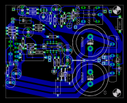
Just be careful about how small you make the spaces between tracks. Some of them look pretty close.
BrianDonegan said:Just be careful about how small you make the spaces between tracks. Some of them look pretty close.
Yeah good point, I am optimizing those right now, but they are not as bad as the image export makes them seem.
Re: Feedback please. 🙂
Good job!
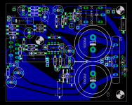
As this seems to be a work in progress, let me try to see what might be improved.
Perhaps filling up all that extra area that you do not seem to be bothered for might be a good thing.
If you put things closer together you may end up with shorter traces, which is always a good thing.
The whole block around the LM318 can be brought up and to the left. That would allow your main PS caps to come forward or have some space for larger types.
There are two things that you did that in all my designs were handled differently:
1) The thin - V track going to pin 5, which I always put it inside between pins 1 to 4.
2) The mute resistor, which you feed it to the left, not allowing you to leave space for the thin - V track mentioned above as track to pin 4 must be thick.
If you above you can have more space to move R3.
In any case, the major thing I do not agree with in this design is putting the bridge and main capacitors in the main board.
PCB design is so compromised, particularly the handling of clean and dirty grounds. Even more when you are now using another chip that needs separate regulators, which also demands another bridge and more large capacitors.
Using a main separate board for the supply, as on BrianGT boards.
Just my 5 cents...
Carlos E. Martínez
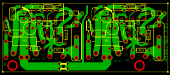
Russ White said:OK, all components on and wired. 🙂 I have a lot of extra space, bu that does not bother me too much. I can probably optimize the power traces a little (make them a touch shorter). Please let me know what you think.
Good job!
As this seems to be a work in progress, let me try to see what might be improved.
Perhaps filling up all that extra area that you do not seem to be bothered for might be a good thing.
If you put things closer together you may end up with shorter traces, which is always a good thing.
The whole block around the LM318 can be brought up and to the left. That would allow your main PS caps to come forward or have some space for larger types.
There are two things that you did that in all my designs were handled differently:
1) The thin - V track going to pin 5, which I always put it inside between pins 1 to 4.
2) The mute resistor, which you feed it to the left, not allowing you to leave space for the thin - V track mentioned above as track to pin 4 must be thick.
If you above you can have more space to move R3.
In any case, the major thing I do not agree with in this design is putting the bridge and main capacitors in the main board.
PCB design is so compromised, particularly the handling of clean and dirty grounds. Even more when you are now using another chip that needs separate regulators, which also demands another bridge and more large capacitors.
Using a main separate board for the supply, as on BrianGT boards.
Just my 5 cents...
Carlos E. Martínez
Thanks Carlos,
The idea of a seperate PS board was floated very early on, and a pin wiring scheme very close to what you suggest was too, but in the end I agree with Mauro's guidelines, and have been attempting to follow them as closely as possible with this design.
The main problem with a seperate PS board is you will always have some ground loop when you do so, especially if it is shared between channels.
As for the power to pin 4 I have stiffened up that trace quite a lot, even more then you could if you ran it from the center/back.
I am still looking at the best way to move the opamp, but I am actually not to worried about the extra/wasted space. as almost all the traces are already almost as short as possible.
Having built Mauro's REV A board with the rectifier on board I can say with confidence it is a sound approach.
Cheers!
Russ
Russ White said:The main problem with a seperate PS board is you will always have some ground loop when you do so, especially if it is shared between channels.
No.
You don't.
Stereo, single or double (external) PSU:
Attachments
carlosfm said:
No.
You don't.
Stereo, single or double (external) PSU:
Yes, I admittedly mispoke, I have had a conversation with Carlmart about this as well. While it is possible to avoid "ground loop" it is certainly not without it's own challenges and compromises.
Russ White said:While it is possible to avoid "ground loop" it is certainly not without it's own challenges and compromises.
There are advantages and disadvantages, as usual.
carlosfm said:
There are advantages and disadvantages, as usual.
If only we could create a situation with only advantages. 😉
Hi.
Has anyone built a case for their Mauro yet? Interested in minimum dimensions. Looks like my toroid will be 120mm diameter. How much clearance should I leave between the tranny and the pcb, and about what internal height will I need in the case.
(I'm getting the cart before the horse here, and starting on the case before I have the pcb or parts) 🙂
Michael
I am building a simple MDF(you can tell I build a lot of speakers) case Today. It is 12" Deep, 4" tall(inside), and 8" Wide. I am not using a torroid though, I am using a PE 48VCT trafo. 🙂
I have already bench tested it, so I know that trafo works great.
I will post pics when I am finished.
Just place the torroid behind the heatsink(fin side) and give it an inch or so a clearance. Get your measurement based on that.
Cheers!
Russ
I have already bench tested it, so I know that trafo works great.
I will post pics when I am finished.
Just place the torroid behind the heatsink(fin side) and give it an inch or so a clearance. Get your measurement based on that.
Cheers!
Russ
I would try it and see how hot it gets. 🙂 It will probably be OK, but I have not run the numbers.
Member
Joined 2003
I will be building Mauro's amp and Russ's FreeBird preamp inside an aluminum case I bought off ebay. The case measures 17"x13"x4" so there will be plenty of room for everything.
- Home
- Amplifiers
- Chip Amps
- My "audiophile" LM3886 approach