DcibeL-
I have one extra parts kit for the Mauro's reference design left. Parts are sourced through DigiKey and Mouser. $55US+shipping if you are interested.
I have one extra parts kit for the Mauro's reference design left. Parts are sourced through DigiKey and Mouser. $55US+shipping if you are interested.
psu
Sorry to drag down this rather high level thread with a newbie question, but can i use a 220 VA, 2x 30 V, 2x 3,75 A transformator instead of a 2x25V one? Would get the 30V rather cheap that's why i'm asking.
and while i'm at it here's another completely OT one: i would like to put the transformer into separate housing and provide power and ground for the amp via external cables. would that be viable or in vain? talking about rather short cables here like 30cm max or so (about 1 feet i think?). EMI scares me 😉
1) No. You will end up with way too much rail voltage.
2) Certainly. A lot of people do that. Keep in mind, however, that in this case ( no pun intended) you will be running AC into the amp case either way, as the rectifier and caps of the psu are opn the main amp board.
2) Certainly. A lot of people do that. Keep in mind, however, that in this case ( no pun intended) you will be running AC into the amp case either way, as the rectifier and caps of the psu are opn the main amp board.
BrianDonegan said:1) No. You will end up with way too much rail voltage.
2) Certainly. A lot of people do that. Keep in mind, however, that in this case ( no pun intended) you will be running AC into the amp case either way, as the rectifier and caps of the psu are opn the main amp board.
1) Hmm okay how does a 25V rail sound then? (18v transformator*1,4 right?)
2) Yeah i would design the case to provide AC and DC (up to three rectifiers switchable by.. well a switch 😀)
With incompatible plugs of course. Too bad i can't fit the 2x18 or whatever volts of the AC output into a XLR cable.. oh wait i can i guess 18-0-18? Still missing ground then though

BrianDonegan said:The schematic calls for a 24VAC transformer, resulting in 33-35VDC rails.
I guess there are 4+ pole xlr connectors..
Wouldn't hurt to put ground on the shielding right?
I should learn to read before posting

Okay thanks, well 24VAC it is i guess
Member
Joined 2003
BrianDonegan said:I have one extra parts kit for the Mauro's reference design left. Parts are sourced through DigiKey and Mouser. $55US+shipping if you are interested.
I would gladly take you up on that, though the parts list I have made from Digikey everything adds up only a few dollars more (everything except resistors that is), then I would have to add brokerage fees when it crosses the border so it would end up costing more. Thanks for the offer though.
Member
Joined 2003
Actually, you know what, I'd like to not have to make as many substitutions as I did. Are all the resistors included in your package? Specifically the power resistors, the smaller ones I can steal from school. As well, I was going to use regular EL caps in place of the low ESR caps because I could not find the proper cap from Digikey. It looks as though Mouser has these caps so I assume you have them in the package.
Drop me an email at rtowsley@shaw.ca. I've changed my mind, I am interested.
Drop me an email at rtowsley@shaw.ca. I've changed my mind, I am interested.
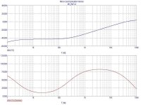
Following the study of the Graham Maynard methods for the amps analysis ,I am preparing of the changes on My_REF, to improve the general linearity and verify his theories.
For anyone doesn't follow the Thread in Solid State forum or on WW, say that is treated of inject a signal on the output of the amp, with the same technique that it uses to measure the DF ( damping factor), to analyse the behaviour in frequency and phase of the amp.
More it is constant the damping and ( over all ) more is constant the phase to all the frequencies, more ( in accordance with Graham and in accordance with me ) gets a sound " clear and equlibrate ".
Graham have works of " class A to AB" solid state, but my circuits serve to show that even a "class B Chips amp" holds the comparison.
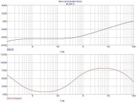
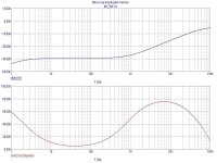
How to introduction, I show you the simulations of the My_Ref "evolution" , till the actual state of my prototype...
Step 1. My_REF "base":
For anyone doesn't follow the Thread in Solid State forum or on WW, say that is treated of inject a signal on the output of the amp, with the same technique that it uses to measure the DF ( damping factor), to analyse the behaviour in frequency and phase of the amp.
More it is constant the damping and ( over all ) more is constant the phase to all the frequencies, more ( in accordance with Graham and in accordance with me ) gets a sound " clear and equlibrate ".
Graham have works of " class A to AB" solid state, but my circuits serve to show that even a "class B Chips amp" holds the comparison.
How to introduction, I show you the simulations of the My_Ref "evolution" , till the actual state of my prototype...
Step 1. My_REF "base":
Attachments

mauropenasa said:Following the study of the Graham Maynard methods for the amps analysis ,I am preparing of the changes on My_REF, to improve the general linearity and verify his theories.
For anyone doesn't follow the Thread in Solid State forum or on WW, say that is treated of inject a signal on the output of the amp, with the same technique that it uses to measure the DF ( damping factor), to analyse the behaviour in frequency and phase of the amp.
More it is constant the damping and ( over all ) more is constant the phase to all the frequencies, more ( in accordance with Graham and in accordance with me ) gets a sound " clear and equlibrate ".
Graham have works of " class A to AB" solid state, but my circuits serve to show that even a "class B Chips amp" holds the comparison.
How to introduction, I show you the simulations of the My_Ref "evolution" , till the actual state of my prototype...
Step 1. My_REF "base":
Yes, after you mention him in your email I read Graham's thread. Very exciting stuff! 😀
I can't wait to see how you implement this!
Thanks for the update Mauro!
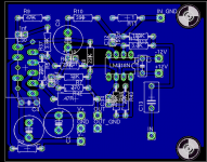
The Rev3 schematic.
R41-R42 reduces the RF "spikes" of the Main PSU ( induced by the SPKs cables ).
C30-C31 are increased to 1nF and R37-R38 reduced to 3k3. This net stabilizes the LM3886 oscillations, reducing the high frequency efficiency of the bridge.
C34+R43 and C35+R44 increase the internal compensation of LM318.
R39-R40 reduce OLG ( open loop gain ) to about 65dB, and the OL BW to about 20Khz.
C10-C25 is the Feed forward that compensates the inductive components of the output bridge, increasing the linearity of the damping.
A better description when finds the time to write it...
Ps. I Suggestion to perform this changes to experienced Diy members, in degree to perform un tests of verification. How to have always written, this circuit is "extreme" and they serve to study any combinations, and to show the level of "audio quality" that is it may reach with the Chips amps. In particular , my objective is the emulation of the class A (A/B) solid state amps...
Ciao
Mauro
Attachments
Wow, thanks for the fast work Mauro, I am designing a PCB around this circuit today. I will test it as soon as I can. 🙂
Using Revision A boards for Rev C
Russ,
Looking it over it looks like there are 4 resisitors and four capacitors added per channel. I hate to do it, but it should be fairly easy to "hillbilly rig" these 16 components to the circuit board.
All are additions, and only the nulling circuit for the LM3886 look to be critical. I may just build and add parts as wanted.
Also, ordered some parts from Parts Express and went ahead and got some of those 5.00 24-0-25 surplus transformers. They are a real chunk of iron. For my needs one should be plenty. Someone estimated them as 200 watt rating. I would guess higher from looks and heft.
I may be started on mine fairly soon, and vacation is coming upo, it will be another month to get one finished. I will post once built and playing.
George
Russ White said:Ok, here is my first try at a layout for one channel of the Revision "C" amp section alone:
Russ,
Looking it over it looks like there are 4 resisitors and four capacitors added per channel. I hate to do it, but it should be fairly easy to "hillbilly rig" these 16 components to the circuit board.
All are additions, and only the nulling circuit for the LM3886 look to be critical. I may just build and add parts as wanted.
Also, ordered some parts from Parts Express and went ahead and got some of those 5.00 24-0-25 surplus transformers. They are a real chunk of iron. For my needs one should be plenty. Someone estimated them as 200 watt rating. I would guess higher from looks and heft.
I may be started on mine fairly soon, and vacation is coming upo, it will be another month to get one finished. I will post once built and playing.
George
- Home
- Amplifiers
- Chip Amps
- My "audiophile" LM3886 approach