After a couple of weeks im gonna try some 15nf EROMAK-1 polycarbonates i have in C7. For the time being i kinda miss the euphoric effect FKC had in C32( replaced with MIAL polystyrene).I hope the pc board can stand the constant abuse
After a couple of weeks im gonna try some 15nf EROMAK-1 polycarbonates i have in C7. For the time being i kinda miss the euphoric effect FKC had in C32( replaced with MIAL polystyrene).I hope the pc board can stand the constant abuse
Polycarbonates can sound wonderful, particularly in C7 and C30.
I don't like them in C32, too much HF emphasis.
But in C7 today the absolute best was that ceramic.
So after all the gyrations and hand-wringing and component pulling, the best solution is what most technical people recommend: a simple ceramic cap directly across the power pins. Who would expect that a ten cent part performs better than a one dollar (or, in ridiculous cases, a hundred dollar) part? I would, for one. Simply throwing gobs of money at a circuit is not always the best way to improve its performance. But sometimes it is (C13)!
Good job, as usual, Dario. Does that finally resolve this issue? Ceramic caps are very good at power supply bypass, with no need for exotic stuff. Try soldering them directly across the pins, if that's possible. I don't have the PCB in front of me, but I've done the same on lots of other chips and it's a very simple task if you're careful of heating time. I might try it on my amps.
What value did you use? Recommended is usually 100nF, just as shown on the original schematic.
Peace,
Tom E
So after all the gyrations and hand-wringing and component pulling, the best solution is what most technical people recommend: a simple ceramic cap directly across the power pins. Who would expect that a ten cent part performs better than a one dollar (or, in ridiculous cases, a hundred dollar) part? I would, for one.
Hi Tom,
It's nice to read you again. 🙂
My answer at the moment is: maybe.
If in the next days I won't find any fault that in this moment I'm overlooking it will be my definitive choice for C7.
BTW sometimes there's simply no better bypass than an otherwise awful ceramic, I've had the same experience with the MINI2496 DAC.
Good job, as usual, Dario. Does that finally resolve this issue?
Thanks Tom 🙂
I really hope so... I'm bored to swap caps in C7... 😀
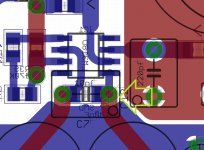
Try soldering them directly across the pins, if that's possible.
Sure it would be possible but in the FE layout they're already really close to the chip (see attachment).
I might try it on my amps.
What value did you use? Recommended is usually 100nF, just as shown on the original schematic.
It would be nice so you could confirm or not. 😉
I've used a 100nF X7R ceramic (probably is an AVX)
Attachments
I think we all just do the best we can, but when I see everyone swapping components like audiophiles swap equipment, I kind of smile.🙂. Certainly helps the economy.soongsc,
I certainly hope you don't think my comments were specifically pointed in your direction, they were not. I totally agree with all you say relating to "you gradually feel interactive emotion" - great description.
My question, stated differently, deals with descriptive terms representing whether caps "truly" add to the product that left the recording studio, or primarily filter what is already there, selectively due to their construction and implementation. I honestly didn't pay a lot of attention to the "why-how" of cap substitutions, and merely noted and enjoyed the results, till I got evolved in swapping a lot of them in the FE beta project. That stirred my curiosity to start thinking about "how" they do it.
I have no doubt your published information is valid and descriptive of your work. My questions/suppositions are at a more general level and maybe from up a thousand feet - how, in the search for the most minimally invasive path between the studio and my ears, do caps do what they do?
Again I may be going way off topic here and will heed Andrew T.'s often expressed answer - go to study hall and let us know what you have learned. 😀
So after all the gyrations and hand-wringing and component pulling, the best solution is what most technical people recommend: a simple ceramic cap directly across the power pins. Who would expect that a ten cent part performs better than a one dollar (or, in ridiculous cases, a hundred dollar) part? I would, for one. Simply throwing gobs of money at a circuit is not always the best way to improve its performance. But sometimes it is (C13)!
Good job, as usual, Dario. Does that finally resolve this issue? Ceramic caps are very good at power supply bypass, with no need for exotic stuff. Try soldering them directly across the pins, if that's possible. I don't have the PCB in front of me, but I've done the same on lots of other chips and it's a very simple task if you're careful of heating time. I might try it on my amps.
What value did you use? Recommended is usually 100nF, just as shown on the original schematic.
Peace,
Tom E
there maybe convenience in thinking what's best for one person is best for everyone, but dario still hasn't tried a teflon in there. 😀
not that i've done vise versa...
perhaps skouliki could solve us this dilema once and for all 😉
we must remember though, that the cap value for c7 does affect tone balance where anything less than .1uf gives anemic bass. so one must detatch this aspect from their observation when swapping around caps of different value.
Last edited:
upon reading up on it, ceramic does sound desirable enough for me to try. i will do this soon enough 😉
Regarding ceramics for decoupling i had also very good results with analog stage on my DAC where only ceramics stopped oscilating the opams. They are also recommended in all NS datasheets for decoupling even they are not prefered in the audio world.
Speaking of capacitors i received some Nichicon FG yesterday and replaced in C9 position (i had a non polar Muse) and also for C1/C2 i replaced the Panasonics with Elna RJH and i must say the results where very audible and positive. I really liked this elcaps upgrade.
Speaking of capacitors i received some Nichicon FG yesterday and replaced in C9 position (i had a non polar Muse) and also for C1/C2 i replaced the Panasonics with Elna RJH and i must say the results where very audible and positive. I really liked this elcaps upgrade.
Speaking of capacitors i received some Nichicon FG yesterday and replaced in C9 position (i had a non polar Muse) and also for C1/C2 i replaced the Panasonics with Elna RJH and i must say the results where very audible and positive. I really liked this elcaps upgrade.
Fine 🙂
dario, what do you think about using these for c9?Mundorf MCap-250 220uF :: M-Cap Series :: Mundorf :: Film / Foil :: Capacitors :: Passive Components :: Electronic Parts :: Banzai Music
dario, what do you think about using these for c9?http://www.banzaimusic.com/Mundorf-MCap-250-220uF-SKU25914.html
If you don't mind having a can of beer on top of your amp...

No major problems. 😉
I wonder if the "toing and froing" with the rail to rail decoupling has been complicated by the omission of rail to power ground decoupling?
The rail to rail decoupling must be very short.
The rail to power ground decoupling must also be very short. The two caps must be connected together with the very shortest link. That junction becomes the Power Ground. The best caps for this decoupling are ceramics. and no they do not need to be C0G/NP0, XR & XY caps can do the job better due to slightly higher esr.
Snake oil or just uniformed spouting?than an otherwise awful ceramic
Last edited:
there maybe convenience in thinking what's best for one person is best for everyone, but dario still hasn't tried a teflon in there. 😀
not that i've done vise versa...
perhaps skouliki could solve us this dilema once and for all 😉
we must remember though, that the cap value for c7 does affect tone balance where anything less than .1uf gives anemic bass. so one must detatch this aspect from their observation when swapping around caps of different value.
The teflons im using are just 22nf but i dont feel there's any bass missing. Certainly not anemic. There is more extension and definition to the upper side of audible spectrum and the bottom end feels well controlled with good punch. These are my listening impressions so far but take into consideration that more listening is required since i installed the teflons the day before yesterday. I think in 2 weeks time i will have a clearer picture about teflons in C7
I wonder if the "toing and froing" with the rail to rail decoupling has been complicated by the omission of rail to power ground decoupling?
Hi Andrew,
I actually think the contrary since the presence of the rail to ground decoupling would have added those caps coloration to the equation.
The rail to rail decoupling must be very short. The two caps must be connected together with the very shortest link. That junction becomes the power Ground.
I'm missing something, Andrew... Which two caps?
In rail to rail there is just one cap...we're talking about C7, right?
The best caps for this decoupling are ceramics. and no they do not need to be C0G/NP0, XR & XY caps can do the job better due to slightly higher esr.
I was just thinking to try also C0G/NP0 caps.
Thanks Andrew, a precious info. 🙂
Snake oil or just uniformed spouting?
None of the above...
From what I know (and I heard) in signal filtering applications a good film cap is usually more linear (and sound much better) than a X7R ceramic.
C0G/NP0s are much better for the linearity problem but sometimes can sound a bit harsh and less detailed.
I have edited my post.
Thanks, now it's more clear.
So, if I understood correctly you're saying that also the rail to ground caps should be ceramics?
Describing a ceramic as awful is wrong.
Just accept that for some uses thge ceramic cannot be bettered.
Just as other caps are the best choice for some duty/ies
Just accept that for some uses thge ceramic cannot be bettered.
Just as other caps are the best choice for some duty/ies
The HF decoupling must be able to pass very high frequencies. The MF decoupling must be able to pass the lower frequencies below those handled by the HF decoupling.............. if I understood correctly you're saying that also the rail to ground caps should be ceramics?
The LF decoupling must pass the audio frequencies.
Each set of decoupling must have the caps chosen to suit the duty.
Who makes the caps or how much they charge for the caps or how many adverts one sees for the caps has no bearing on the duty that the cap suits. The specification rules, not the name on the label.
From what I know (and I heard) in signal filtering applications a good film cap is usually more linear (and sound much better) than a X7R ceramic.
.
Just to return to my question of yesterday for a quick second, can someone explain (other than the reservoir function) when/what application does a cap does not act as a filter?
Haven't had time to get to study hall yet.🙂
Last edited:
Describing a ceramic as awful is wrong.
Just accept that for some uses thge ceramic cannot be bettered.
Just as other caps are the best choice for some duty/ies
I already accept it...but sometimes we forget what we already know... 😉
Thanks for the informative post. 🙂
- Home
- Amplifiers
- Chip Amps
- My "audiophile" LM3886 approach