For C13, has anyone tried the Mundorf Silver/Gold?
Tom (Madisonears) has tried one of those high-end Mundorf.
How interesting. The original MyRef C had the glitch, but the high frequency glitch is only in one location.
...
I think the next test I'm going to add snubbers to my PS as I have on the other amp.
Definitely interesting. 😎
So I suppose we can say that both LM3886 grounding schemes are the same regarding the glitch. 😉
Since you're using a SMPS can you exclude it for such glithc?
BTW I think the problem lies in the PCB layout, Mauro original one was different and none of his graph shown that glitch, if I remember correctly.
I think it is important to also consider what kind of stimulation is used. This will most likely not show up if we use a swept sine signal. Since I use MLS, the nature of stimulant is more complicated. Additionally, I have 22ohm across the inputs instead of having them shorted. If we compare this with my open input measurements, we can see some similarity in the locations of the glitches.
Whether it can be the power supply or not is another question. But with the switching frequency above 70KHz, I think the possibility is very low. To me, it seems like some interaction in the amplifier loop. Whether it is due to interaction between the input and the output coupled with the mains is another thing to investigate.
Whether it can be the power supply or not is another question. But with the switching frequency above 70KHz, I think the possibility is very low. To me, it seems like some interaction in the amplifier loop. Whether it is due to interaction between the input and the output coupled with the mains is another thing to investigate.
investigating any of these possible influences is made much more difficult by having the PSU and Main Audio Ground on board.... To me, it seems like some interaction in the amplifier loop. Whether it is due to interaction between the input and the output coupled with the mains is another thing to investigate.
An externally hosted image should be here but it was not working when we last tested it.
With this kind of arrangement, I am almost certain that the output and input are forming some kind of loop. But I need to move the input lines around to verify it.
To me, it seems like some interaction in the amplifier loop. Whether it is due to interaction between the input and the output coupled with the mains is another thing to investigate.
This, IMHO, points to the PCB layout again...
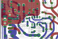
See the attached magnification of TP board, the V+ trace overlaps LM3886 output trace so there is a capacitive coupling (I hope the term is correct) between them.
It's for that reason that in the Fremen Edition I've differently routed V+ trace.
Also, OUT connector is very close to the compensation network so, possibly, the higher capacitance of the alternate compensation helps somewhat...
Attachments
The last time I agreed to do this for a friend, his board sat around for 7 months before I got around to fixing it (a day or two) and shipping it back.
You're better off in getting it fixed in the US. Ask troystg or udailey or others on this forum for help - if they can't do it, they'll at least give some pointers.
I'll start with my 2c: Check R11, the 1-ohm lift resistor between the small-signal ground and PGND. If it's open, it's likely that merely replacing it will fix the MyRef.
I'll be happy to supply the parts for the Rev E mod, as well as the LF01 modules, after your boards are fixed.
My My_Ref is now working. 😀 siva, thank you sir.
What baffles me is why it occurs as multiples of 60Hz.
That's an easy one - they're harmonics of the 60 Hz AC hum. The 60 Hz goes through a round of amplification through the opamp and chipamp, where there will be a small amount of H2, H3, etc. that are generated due to slight non-linearities in the gain stage. These will then be attenuated by the feedback network and returned to the input stage LTP, where further inter-modulation will occur with the 60 Hz from the input. Coupling between the speaker-out leads and the input is another source of feedback.
In short: The harmonics are the cumulative effect of small non-linearities in the gain stages combined with GNFB.
My My_Ref is now working. 😀 siva, thank you sir.
You're welcome - please provide more details of what had actually failed, and how it was fixed.
The only thing is 60Hz does not show up on the real time spectrum analyzer.That's an easy one - they're harmonics of the 60 Hz AC hum. The 60 Hz goes through a round of amplification through the opamp and chipamp, where there will be a small amount of H2, H3, etc. that are generated due to slight non-linearities in the gain stage. These will then be attenuated by the feedback network and returned to the input stage LTP, where further inter-modulation will occur with the 60 Hz from the input. Coupling between the speaker-out leads and the input is another source of feedback.
In short: The harmonics are the cumulative effect of small non-linearities in the gain stages combined with GNFB.
we usually see the odd harmonics of the mains frequency in the spectrum.
Surprisingly, the second harmonic and the fundamental are often well suppressed.
This is probably due to the high feedback generally available at lower frequencies to improve PSRR
Surprisingly, the second harmonic and the fundamental are often well suppressed.
This is probably due to the high feedback generally available at lower frequencies to improve PSRR
You're welcome - please provide more details of what had actually failed, and how it was fixed.
R11 had infinite resistance on both boards. Replacing only these two 1 ohm fixed the My_Ref ! You said it would be a 50/50 shot.
I could not find the resistors localy and wanted a better soldering station so I ordered from Parts Express. Got a Stahl gun w/ variable temp and 4 tips (one is a small chisel tip) for 17usd, got a desoldering tube (push button) and a 10 pack of 1R 1/2W resistors.
My desoldering skills are terrible. I broke a leg on the first board but the resistor removed intact on the second board. There was some solder left in the thru-holes that I could not remove with the tube or with a wick. I ended up using a sewing needle on the top pad while I heated from underneath. I then used a tiny needle file to open the thru-hole enough to fit the component. I have much to learn.
Next up, I want to build a case. A tray with a cover really so I can properly ground the amp and mount my junky E-core KTC transformer. Then, I want to build a bulb testor with a switch by the socket.
My goal is to build a receiver using my Sony XRF-F1HD tuner. I have a Twisted Pair Darwin source selector kit that I would like to use to switch between the tuner and a AK4396 DAC (dipped in Sapho). Then the signal would go to a Lightspeed volume powered by regiregi22's parasite circuit. I want a powered potentiometer and circuit that can receive remote control from my Dish 722 remote. I want this signal to go to a 600mA DCB1 and into the My_Ref and use the minimun number of good quality transformers to power it all. I want to keep the tuner chassis/case intact (class 2) and build a larger case around it with a extended front panel for controls.
My boards are the small Twisted Pair green boards with AC2 PGND AC1 at the edge of the board next to the big single B1. I'm thinking of mounting the boards 90* on L brackets to make moving components under-board easily done, making room for FE boards later. I would like to have the buffer's irfp 9240 & 240 on the same heatsinks as the My_Ref and have the fins outside the case. Transformers at the front, PS and smoothing caps in the middle and DAC and signal at the back.
I'm sorry I was so wordy; this post probably belongs in the construction forum but I think proper (located) construction and safety can improve the sound. Thanx again for putting up with the n00bie. 😱
I have verified the 60Hz glitch changes with moving input wire around. So it seems output and input wiring need to be away from each other. Why it couple around 60Hz is still unknown. Could be something in between the loop and power ground. My case is metal, with it floating, there could also be some interaction.
I have selected as a temporary reference C13, a REL CAP ppmf rated at 250V 2.5A, which I had laying around. It brings the sound closer to what I am looking for compared to the original TP BOM. It is bypassed by a 0.01uF Wima FKS.
Hi. I recently acquired two V1.2 boards and have a question about C9. I know that the suggested cap is a 220uf blackgate STD. I have in my possession some BG STD 50v 330uf, would it be ok to use them ? Also does someone have an opinion about using an MKT1822 (bypassed with an mkp1837 or russian ft1) in C13? Thanks
Hi. I recently acquired two V1.2 boards and have a question about C9. I know that the suggested cap is a 220uf blackgate STD. I have in my possession some BG STD 50v 330uf, would it be ok to use them ?
Yes.
Also does someone have an opinion about using an MKT1822 (bypassed with an mkp1837 or russian ft1) in C13? Thanks
An MKT1822 could be ok but do a favour to yourself and don't use the MKP1837 bypass... 😉
Also a cheap russian K73-16 is a nice choice but a film/foil cap such a Mundorf Zn or an Audyn KP-Sn will be in another league.
Thanks for your answers dario. Eventually i will try to get a better cap in c13 like a mundorf zn but today i ordered the 10000uf Mundorfs and my wallet took a serious hit! Hope they worth it
Thanks for your answers dario.
You're welcome 🙂
Eventually i will try to get a better cap in c13 like a mundorf zn but today i ordered the 10000uf Mundorfs and my wallet took a serious hit! Hope they worth it
The Mundorf AGs are worth the price but only after you've optimized the rest, IMHO.
I would have buyed first a good cap for C13, which is one of the most important positions.
Anyway don't worry, even with a medium quality cap like a Mundorf MCAP or a K73-16 you'll hear AGs.
The only caveat is that you'll enjoy full advantage only after C13 is populated with a good cap.
Forgot to ask one more thing. Would it be worthwhile to use 0.1uf BGnxHiQ in positions C4 and C5?
Forgot to ask one more thing. Would it be worthwhile to use 0.1uf BGnxHiQ in positions C4 and C5?
I don't know, never tried them.
- Home
- Amplifiers
- Chip Amps
- My "audiophile" LM3886 approach