Thanks! It seems the circuit is too complicated for me to understand.
In that case it won't need an active pre, and a simple 50k attenuator between the amp and the source would be fine.
Regards
Asen
In that case it won't need an active pre, and a simple 50k attenuator between the amp and the source would be fine.
Regards
Asen
It helps to think of it as one big high current opamp in non-inverting mode. The two opamps really operate as a single unit.
EDIT: this is also why the common PS is important. The LM318 common supply actually works to help eliminate some noise/distortion. It is a very well thought out yet very simple power supply approach. It just proves that things don't have to be complex to be the best of class.
EDIT: this is also why the common PS is important. The LM318 common supply actually works to help eliminate some noise/distortion. It is a very well thought out yet very simple power supply approach. It just proves that things don't have to be complex to be the best of class.
Help me fix my RevCs
Months ago I killed my RevCs, accidently shortcut them. I replaced Q2, Q3, Q4 but this doesn´t help. What makes me wonder is that I hear the relays switching at shutoff, but not when turning on.
Where to measure what to figure out the fault ?
😕 Gerd
Months ago I killed my RevCs, accidently shortcut them. I replaced Q2, Q3, Q4 but this doesn´t help. What makes me wonder is that I hear the relays switching at shutoff, but not when turning on.
Where to measure what to figure out the fault ?
😕 Gerd
Hi,
during my experiments I managed to kill twice my My_Ref, the things that failed were the 1 Ohm resistor between signal and power gnd and once the LM318.
The 3886 is hard to kill.
Cheers
Andrea
during my experiments I managed to kill twice my My_Ref, the things that failed were the 1 Ohm resistor between signal and power gnd and once the LM318.
The 3886 is hard to kill.
Cheers
Andrea
Hi Andrea !
Read your reply, looked at R11 and found it fried on one board.
I changed both and ...
 THANKS !!!
One Channel came back to life, the other didn´t. There must be wrong something else. 🙄
Read your reply, looked at R11 and found it fried on one board.
I changed both and ...
THANKS !!! One Channel came back to life, the other didn´t. There must be wrong something else. 🙄
Hi,
which kind of fault has the other channel? (Dc, heatinc components, ecc.)
Measure some voltages (supply of LM318, its output, ecc.) and see if there are anomalies.
You can try to swap the LM318 and if the fault changes channel you've found the culprit.
IIRC someone even fried a rectifier bridge (not me)
Cheers
Andrea
Can´t do further checks before tonight, got to earn money for spare parts.
If the LM318 was faulty, wouldn´t the relay switch on powering up anyway ? No click to be heard ...
Cheers,
Gerd
If the LM318 was faulty, wouldn´t the relay switch on powering up anyway ? No click to be heard ...
Cheers,
Gerd
HI Gerd,
Ok some basics. Forgive me I know you probably have done some of this already, but this is for other's benefit as well.
Measure voltage between relay power pins if possible.
Also make sure that the relay is actually switching. A relay that has been subjected to too much current can have it's contacts vaporized. Just clicking does not indicate it is functioning correctly. When the relay is on there should be no resistance beween the OG terminal and PGND.
Also check the voltage to LM318 and LM3886.
Measure resistance between OUT and OGND. It should be very high.
Measure all the low value and power resistors (470ohm, 1.5K, 1R) and be sure they are OK.
I may be able to think of other things to check later, but hat should cover it for now.
Cheers!
Russ
AAAAHHH !!!! (Followed by a squall of untranslatable german cusswords)
Measured any R value - all are fine. Powered ´em up to measure voltages and ... I shortened pin 7 and 8 of LM318 of the working one and that was it. Two dead RevC boards again. **** ! I´m as thick as a plank. Holy **** ...
I´m just draining my 3rd Becks, then I´ll continue bawling.
Good night, folks!
Measured any R value - all are fine. Powered ´em up to measure voltages and
... I shortened pin 7 and 8 of LM318 of the working one and that was it. Two dead RevC boards again. **** ! I´m as thick as a plank. Holy **** ...I´m just draining my 3rd Becks, then I´ll continue bawling.
Good night, folks!
OMG Gerd, talk about bad luck. About like the like I have been having lately. I will indulge in a sympathy Becks in your behalf as well. 
Sorry mate.
Russ
I will indulge in a sympathy Becks in your behalf as well. Sorry mate.
Russ
@ Russ: Thanks for compassion, balm to my wound 
@ Andrea: How long did you search the fault ? 😉
We will never surrender ...
Cheers !
@ Andrea: How long did you search the fault ? 😉
We will never surrender ...
Cheers !
SmellOfPoo said:
@ Andrea: How long did you search the fault ? 😉
We will never surrender ...
Cheers !
I just followed the smell (of burnt)


Cheers
Andrea
Great thread guys. One of the best I've ever read, alongside "gravity well of a dark star" on audiocircle, and "building high end turntables at home despot for $200" on audiogon. Unfortunately the gravity thread died but the home despot thread is also alive and kicking. Listening to my first ever soldering project, a modded and rehoused S Impact amp now, and looking for a high end project. I'm really a tube guy but this project seems to good to miss.
SmellOfPoo said:AAAAHHH !!!! (Followed by a squall of untranslatable german cusswords)
Measured any R value - all are fine. Powered ´em up to measure voltages and
I´m just draining my 3rd Becks, then I´ll continue bawling.
Good night, folks!
There comes a time in analog electronics when one invests in variable supplies and a variac ....
Maybe your time is due? 😉
(After all, you still have the beer)
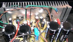
New one in operation
I read the glowing reports in the Absolute Sound of the Emitter II. Looking at it, it had to be the four chassis implimentation that gives it the reported great sound.
So to build my own, for 25,600.00 less money here is my version. The idea is the same. One chassis for active circuitry, two seperate output power supplies, a battery supply for the input stages.
I was able to save the 25,600.00 by purchasing my boards from TP!
Attachments
![dsc00405[1].jpg](/community/data/attachments/66/66601-c1a402447f748c85dc1ea2e4ebbe8119.jpg?hash=waQCRH90jI)
![dsc00404[1].jpg](/community/data/attachments/66/66611-f8cbb7ca0ca528008e26fa22980ff9e2.jpg?hash=-Mu3ygylKA)
- Home
- Amplifiers
- Chip Amps
- My "audiophile" LM3886 approach