Let's take a look at the well-known law of induction, turn ...
 and remember what the coefficient of self-induction called inductance actually expresses and what it is directly dependent on. I think that puts modeling and, above all, absolutism back in perspective. In short, the coefficient L(tc) cannot be constant (in sampling mode as transducer_coil or our electrical tests).
The challenge now is to represent this coil (an N wire winding on a soft magnetic iron core) as a lumped model in such a way that it can correctly model a wide load spectrum.
The challenge now is to represent this coil (an N wire winding on a soft magnetic iron core) as a lumped model in such a way that it can correctly model a wide load spectrum.
Wouldn't it even be advantageous if the parameters were determined with a constant current flow? If so, then the next question is the absolute value of this current flow.Yes, you need to measure with as small an excitation as you can; a cartridge has tiny coils and a core that is easily saturated. Fortunately, with constant voltage excitation, the impedance is enough to limit current.
But I am patiently waiting for your measurement results on this academic but very exciting subject: measurement technology.
Many thanks in advance
HBt.
OK, so we go back to hysteresis loops and note that inductance changes with flux density. But I think in a moving magnet cartridge, the flux density is pretty feeble, which is why I think one should test at as low a level as practicable. I think the changes in inductance we see in a cartridge are down to hysteresis loss goin g round the loop (rather than up and down it) and to eddy current effects. I await new tester impatiently. Naturally, tomorrow is a Bank Holiday.

Hello EC8010,
how is your new analyzer performing? I'm very interested in your results, maybe you can record curves with different excitation levels - because then the tiresome argument (with H. P. or others) might be off the table for once.
With thanks in advance,
HBt.
how is your new analyzer performing? I'm very interested in your results, maybe you can record curves with different excitation levels - because then the tiresome argument (with H. P. or others) might be off the table for once.
With thanks in advance,
HBt.
New analyzer has yet to arrive. I am not a happy bunny, having been told "one week" two weeks ago and now being told "Maybe next week". Apparently, it is scheduled to leave Germany on Friday, on arrival at UK distributor, it will be sent to me. If I believe what I'm being told. I'm a little twitchy about different excitation levels. If I can do smaller than I have presently used, that will be fine, but I don't want to wreck a cartridge.
Supply chain problems are always a nuisance, I'm sorry for you. I have only ever had good experiences with CalPlus GmbH in the past. I hope the problem is not caused by my fellow countrymen.
Let's just hope for the best.
For loading the pickup:
I too am always overly cautious about the level, but if we look at the DC resistance and assume a wire cross-section of 0.314e-3 mm^2, then my old table book says that 10mA is the limit of continuous loading. So 50mW should signal the end. What does Ortofon itself say about this, what wire cross-section do they wind?
20µApp to 200µApp should be feasible without any concerns. If not significantly more (up to 1mApp, and I think we will see big differences here.
I think it's general incompetence and sloppiness, all the way from Japan, through Germany, and to the UK. But it seriously annoys me that I placed the order on a promise of one week lead time that has been broken.
I've never yet managed to get any information from Ortofon, and can't imagine they'd suddenly be helpful. Once upon a time, I would have sacrificed a cartridge to science to determine wire diameter, but they're too expensive now. Analyser is constant voltage, the option of constant current drive would require an entire redesign not just of the drive but also of the sense. I would imagine that's true of all analysers.
I've never yet managed to get any information from Ortofon, and can't imagine they'd suddenly be helpful. Once upon a time, I would have sacrificed a cartridge to science to determine wire diameter, but they're too expensive now. Analyser is constant voltage, the option of constant current drive would require an entire redesign not just of the drive but also of the sense. I would imagine that's true of all analysers.
By the way, if you haven't read it, this HP/Agilent/Keysight application note is excellent:
https://www.cmc.ca/wp-content/uploa...chnologies-impedance-measurement-handbook.pdf
https://www.cmc.ca/wp-content/uploa...chnologies-impedance-measurement-handbook.pdf
In fact, I was not aware of this phantastically summarizing compendium. It brings back so many memories of better days than the present - life is passing by.
thx
Here we can find all the questions that some users and authors (here in the forum) are simply not prepared to answer regarding their modeling and measurement recording. Normally, the entire measuring system, parameterization and chain are named.
thx
Here we can find all the questions that some users and authors (here in the forum) are simply not prepared to answer regarding their modeling and measurement recording. Normally, the entire measuring system, parameterization and chain are named.
Yes, it is very good. It mentions short-circuit and open-circuit calibration. For my test set-up, I have short and open circuit sweeps. The short-circuit sweep reveals a little lead inductance and some skin effect and the measurement spreadsheet subtracts these series components whilst in A + jB form. The open-circuit sweep reveals a 0.005pF stray shunt capacitance, in parallel with 100G that is due to the analyser's noise floor, but (so far) I do not attempt to correct for these parallel components.
When the new analyser arrives, I will derive new corrections. Hopefully, the noise floor will be lower, revealed by a larger shunt resistance.
When the new analyser arrives, I will derive new corrections. Hopefully, the noise floor will be lower, revealed by a larger shunt resistance.
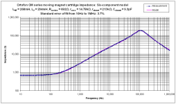
After a lot of stress, it finally arrived, three weeks late. I finished making a screened test jig for it yesterday. I have successfully driven the tester from computer and swept stuff from 4Hz to 8MHz. I can confirm that my original six-component model is correct; I fitted an Ortofon OM cartridge from 10Hz to 1MHz. (Didn't go to 8MHz because it just didn't seem necessary - 1MHz is good enough for audio!)
I can confirm that my original six-component model is correct; I fitted an Ortofon OM cartridge from 10Hz to 1MHz. (Didn't go to 8MHz because it just didn't seem necessary - 1MHz is good enough for audio!)
Many thanks for your efforts EC8010
About your latest results:
immediately raises a plausibility question, because an ideal parallel capacitance, a global Cp, always leads to the resulting impedance decreasing with increasing frequency.
And it is precisely this behaviour that contradicts real physical procedures, i.e. nature.
Ultimately, this thread also revolves around the question of the usefulness of the known chained four-pole models of an LT-Spice user.
Would you like to post the determined impedance curve of the measuring system here, with the phase?
By the way, I can still remember my communications engineering laboratories very well; designing usable component test setups is often very time-consuming.
HBt.
Indeed parallel capacitance leads to impedance falling with frequency, as shown. But that makes sense to me because I expect to see stray capacitance across the coils. I believe the impedance is determined purely by the electrical parameters of the coils and that the coupling from the mechanical system is so weak that its effect is not measurable. When I am happy that my test setup is as good as it can be, I will try comparing measurements with and without the stylus inserted. I've not bothered plotting phase because in a linear system, all the information can be gleaned from the more intuitive plot of Z.
You are correct: Designing and building a good test jig takes considerable time and effort. But it repays you every time you use it.
You are correct: Designing and building a good test jig takes considerable time and effort. But it repays you every time you use it.
Attachments
- Home
- Source & Line
- Analogue Source
- My AT420E(OCC) Cartridge - a confused look at the electrical side