Okay, I see what you're saying... So then it would be more feasible to make a class ab using my other transistors, I do however need info on how to work with long tailed pairs and global feedback, since they seem so important... Even if someone could help with my diagrams and numbers...
If you use your 3055's, you'll need to go single ended, and I don't know much about that topology (but I'm sure someone out there does), but I do know that in class AB mode, complementary stages are better (actually, there may be some controversy there), so it would be more feasible to either use your Japanese transistors or get MJ2955s to go with your 2N3055s.
Just like in an integrated opamp, you need global negative feedback coming back into your long tailed pair (diff. amp), or the circuit becomes a comparator. It would take all day to go into all the details, Geoff and I told you some of the the basics in your other thread. With that info, you can design simple amps. I think you can learn alot by studying that schematic and others, as long as you know what everything does, you can use ohm's law to see what's going on in the circuit and what values are practical. Slone's book does a much better job of explaining all this, it tells you about compensation, current mirrors, and all that fun stuff, but it's got over 400 7" by 9" pages. It's worth the read though.
Just like in an integrated opamp, you need global negative feedback coming back into your long tailed pair (diff. amp), or the circuit becomes a comparator. It would take all day to go into all the details, Geoff and I told you some of the the basics in your other thread. With that info, you can design simple amps. I think you can learn alot by studying that schematic and others, as long as you know what everything does, you can use ohm's law to see what's going on in the circuit and what values are practical. Slone's book does a much better job of explaining all this, it tells you about compensation, current mirrors, and all that fun stuff, but it's got over 400 7" by 9" pages. It's worth the read though.
Quote:
"If you use your 3055's, you'll need to go single ended, ..."
Why? What is wrong with a quasi-complementary output stage operating in push-pull?
"If you use your 3055's, you'll need to go single ended, ..."
Why? What is wrong with a quasi-complementary output stage operating in push-pull?
If you want to go Class AB, you must go push/pull you have no choice.
If you want to use the 3055's in the output, you'd have to use a quasi complementary output stage.
EDIT:
Geoff, I see you beat me too it 🙂
If you want to use the 3055's in the output, you'd have to use a quasi complementary output stage.
EDIT:
Geoff, I see you beat me too it 🙂
You would use either single ended (class A) or quasi-comp stage. Complementary beats them all for what you want to do. That's what I mean.
Okay, well, I've decided to do complimentary, since I myself have a better understanding of the topic and I don't know much about quasi comp circuitry. I know I could get a good lot of power out of the japanese transistors so I'll use them... I see what you mean bi big comparator, I've had that problem before but couldn't figure it out. Only thing is, I need to know how to implement a longtailed pair, I do understand that it's a diff amplifier and what it's doing on a basic level. But I have troubles with the math of that part. Also, I'm not sure how to work with bias for direct coupling of a push pull pair... I was thinking the usual two diodes forward biased between the bases of the O/T pair, but I guess that's not a very good idea is it?
You could use quasi complementary and bias it high enough so that it runs in class A for low level listening. When the need for power kicks in then it will automatically change to class AB.
You should use a current generator i the diff amp. Once that is done you know the current through the pair and you have only to use Ohm's law.
/Marcus
You should use a current generator i the diff amp. Once that is done you know the current through the pair and you have only to use Ohm's law.
/Marcus
Thanks for the info, I think automatic level switching quasi and constant current sink for the long tailed pair sounds great, that's what I'll try... Though, I think I might just use my japanese matched complimentary pairs for the output, but I think it would still be able to switch to a lower bias when run hard, don't you?
Well, you don't switch bias. If you set the bias current in the output pair to, say, 1 A then it will always be 1 A. So if at low listening levels the current drawn by the speaker is below 1 A then you have a class A amp. But when you turn up the volume the current drawn will be greater than 1 A and you are now in class AB.
All class AB amps work like this. The only difference is that they usually have only some mA in bias current to keep the efficiency as high as possible.
Hope this helps.
/Marcus
All class AB amps work like this. The only difference is that they usually have only some mA in bias current to keep the efficiency as high as possible.
Hope this helps.
/Marcus
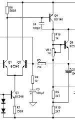
There's not a lot of values to calculate in diff amps themselves, just the tail current, half of which goes through each transistor. This can be determined by a simple resistor, or a constant current source of some sort. There is much controversy over which is better, but a resistor is sure simpler. You can also use two diff amps and two VA stages, called a mirror topology.
In this constant current source, the voltage drop of the diodes - the Vbe drop of Q3 = the total voltage drop across R7. The voltage drop across them would be about 1.34V. 1.34 - Q3's voltage drop of about 0.67 = 0.67V across R7. A simple ohms law calculation, 0.67/150 = 4.4mA. Half this is the quiescent current of Q1 or Q2.
The current that you would want here is based on how fast you can charge the dominant pole cap, C4. There's a formula for figuring out how much current you need.
I = 6.28 x f x C4(farrads) x peak VA output voltage.
So for example, at 50kHz, with C4 as 100pF, or 1e-10F, 6.28 x 1e-10 x 50,000 = 0.0000314.
If you have a 65V supply, you might expect maybe 60V peak from the VA, so 0.0000314 x 60 = 0.001884.
So you need about 1.9mA through the each leg, about 3.8mA tail current.
C4 refers to the Dominant Pole cap, I think that's usually from the
base to the collector of the VAS transistor...
base to the collector of the VAS transistor...
Yes, that is quite obvious as he said that in the post. 🙂 But since he refers to components named Q1, Q2 etc I thought that he maybe had a specific schematic in mind.
Sorry about that, I forgot to post the image. Then I was trying to get back ASAP and my computer had to go and freeze up on me, and it's like 1:21 in the morning too. It's sooooo frustrating!!!!
Anyway, you've all been doing some posting as I type, so I might be a bit behind. I hope this helps.
P.S. Maybe someone should check me on this stuff, just in case.
Anyway, you've all been doing some posting as I type, so I might be a bit behind. I hope this helps.
P.S. Maybe someone should check me on this stuff, just in case.
Attachments
I see that we all go to Rod Elliot's site for knowledge. 😀
Haven't found anyone to beat it yet.
/Marcus
Haven't found anyone to beat it yet.
/Marcus
Good point!😀 I have scoured each and every one of his amplifier diagrams over and over. I learned quite a bit just by some reverse engineering of what he has done. If I had the parts(or could afford them) I would build some of his bigger amplifiers quite happily. Every time I need a pointer, I usually go to esp first!😉
Yup, nothing beats project3a (or mods of it, like seen above) for educational purposes, or for a good, simple amp to build. When I needed plans for a switching supply for car amps, where did I turn? When I need plans for a VU/PPM meter, where did I turn? When I was first learning audio, where did I turn? The list goes on and on! One thing anwers all of these questions: Rod Elliot's site.
- Status
- Not open for further replies.
- Home
- Amplifiers
- Solid State
- My amplifier ideas (crazy)