The output stage did not die as I changed the drivers to KSC2690A and KSA1220A which handle 120V, the vas seems to draw more current when I increased the value of R27 from 440R to 550R (to decrease gain).

Sorry I didn't mean the output stage blew itself, I was meaning if it were connected to a loudspeaker it's likely that it could have blown.
Altering R27 shouldn't, as far as I am aware, affect the current going through the VAS. Altering the rail voltages up to 43 volts will and will also afffect the biasing current through the output pair. You have also removed the VAS buffer/darlington which will affect the performance. The KSC3503 is an excellent VAS transistor and will function fine in higher power amplifiers even without an output triple. The fact the previous one blew means you need to figure out why, it could have simply been destroyed as a result of the drivers letting out the magic smoke.
You need to re-bias the output stage of the amplifier too.

You think that it will affect performance by taking out T5 it seems to slew just as fast, it makes a good square wave up to 100KHz, I cannot get the amp to stop oscillating with T5 in place. the hfe of the drivers and vas is 100-300 should that make up for removing T5.
You think that it will affect performance by taking out T5 it seems to slew just as fast, it makes a good square wave up to 100KHz, I cannot get the amp to stop oscillating with T5 in place. the hfe of the drivers and vas is 100-300 should that make up for removing T5.
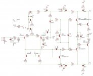
If I am understanding you correctly you removed T5 (U$5) in the posted schematic? This is the VBE multiplier which provides no gain at all and removing and shorting it out turns the amplifier into a class B amplifier, am I understanding you right? (Noting that this changes/reduces the small signal transconductance of the output stage as well) When you say you can't prevent the amp from oscillating you have done an analysis of phase margin against gain & frequency (yee old bode plot) and adjusted the miller capacitor C15 and the other compensation components (C2) which are found in the feedback loop? (Or taken a more seat of the pants approach? 😀) Have you tried split miller compensation or anything other than the original implementation? How about some build pix so we can see what other issues might exist? I've found the cap in location C2 to cause no end of mischief in most amplifier designs. Zobel networks and a small inductor on the output can also help..
Buffering the VAS transistor increases the VAS' ability to drive the output stage, I don't think it affects the slew rate but it will affect the distortion at low frequencies. As far as I am aware buffering the VAS like that will affect stability and possibly the loop gain, changing to different transistors could also affect the open loop gain such that, Cdom in this case, C15 @ 39pf might not be large enough to bring the amplifier back to unity within an acceptable phase margin. Try increasing the value of C15 to say 100pf and see if that helps with stability.
I noticed that you chose to lower C15 down to 39pf and that the original amp did in fact use a 100pf cap, put it back.
I noticed that you chose to lower C15 down to 39pf and that the original amp did in fact use a 100pf cap, put it back.
If I am understanding you correctly you removed T5 (U$5) in the posted schematic? This is the VBE multiplier and removing and shorting it out turns the amplifier into a class B amplifier, am I understanding you right? When you say you can't prevent the amp from oscillating you have done an analysis of phase margin against gain & frequency (yee old bode plot) and adjusted the miller capacitor and other compensation components in the feedback loop? (Or a more seat of the pants approach? 😀) Have you tried split miller compensation or anything other than the original implementation? How about some build pix so we can see what other issues might exist?
He and I were referring to T5 from the original schematic. T5 is the VAS buffer or darlington. No I don't think he's simulated this and plotted stability. 39pf is too small of a Cdom cap to ensure stability, at least in a typical three stage blameless LIN.
He and I were referring to T5 from the original schematic. T5 is the VAS buffer or darlington. No I don't think he's simulated this and plotted stability. 39pf is too small of a Cdom cap to ensure stability, at least in a typical three stage blameless LIN.
Explains a lot I guess.. 😀
Greg's Web Site
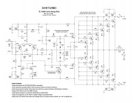
Whilst we're still struggling to get a current check, have a look at this, if you haven't checked the original HRII design. Ever adventurous with BD139/40, DX allows a supply up to 43V, But!!.....
Look at the cap multipliers or regs or whatever on the rails to the front end. What is the supply to the front end CCS and VAS now? I'd say it's fixed at a few volts lower for both stages, keeping them at the lowest supply range voltage. Perhaps we all realised this but it does change operating conditions a bit. Perhaps you would rig this up on a board benproii and see what the original design is actually capable of.
The problem of just swapping everything to higher ratings to cover the transformer windings you think will help you, is that it does nothing to remove the bias errors. The volume level won't change noticeably so what are you trying to do there but dig a deeper hole. Set the bias currents correctly or stare at the smoke. Oscillation is a gain or Ft issue. It won't be an issue unless it is increased in changing parts.
Whizgeek, you could pass me one of those beers down here at #70 😀
Last edited:
The buffered VAS is worth keeping. In that case I'd probably lose C2 and increase C15 to at least 68pF. I'd want to simulate it if I was doing such major design changes though.
Running one pair of outputs at 42V is risky - don't try to drive 4 ohm loads or difficult loads. It's worth adding another pair for peace of mind. As for the amps that run high voltages on just one pair, they are designed so that the supply will collapse if a hard load is driven.
Running one pair of outputs at 42V is risky - don't try to drive 4 ohm loads or difficult loads. It's worth adding another pair for peace of mind. As for the amps that run high voltages on just one pair, they are designed so that the supply will collapse if a hard load is driven.
Does the bootstrap capacitor C13 matter that it's 100uF and not 47uF like in the original circuit.
bootstrap caps can differ from 47uf to 330uf..so the circuit would be ok with say 100uf to 220uf. regrading running one pair of o/p devices on 42+/- volts will work, Back in the early 90's I worked on laney amps/ carsbro/viper/and H/H ma100 head unit's and the supply rail's 47+/- volts.. the laney's o/p was 150w at 4 ohm's rms using a pair of t-03 types. it's all down to how the circuit is designed.
The problem of advocating high voltage supplies is the critical match to transformer size for the necessary supply sag to avert SOA disasters. This is likely beyond the resources and counter-intuitive to typical DIY sound quality notions.
The issue here is of Vceo of the original design transistors and the now unregulated supplies to the front end that allow the bias currents to vary with the supply voltage. If that is not addressed, we have smoke or distortion and bandwidth/stability issues No doubt, you have found 80V drivers and VAS transistors do have limits even if some people push beyond them with success.
If we simply push components above their limits because some have success with this will everyone using such unqualified parts have the same success?
I found out how to run the circuit stably with the vas buffer.
I changed all the drivers and vas for the KSC2690/1220 which are rated for 120V I removed the 10pF on the NFB resistor and changed the miller comp to 150pF. With this configuration it still oscillated, so I changed the vas buffer from BC546B to MPSA42 and the oscillation stopped.
does anybody know what the idle current should be it's at 43ma right now at 43V+/- should it be higher or lower than that.
300w vs 800w? 8db? Well it wasn't voltage. On the little amp, where did your current go?Maybe the speakers are just much less efficient than whatever you were using previously. When running 150 W/ch into my 4-Ohm Magnepan MG-12 speakers (supposedly rated 86dB/2.83v/m @500Hz), my amp would start to clip before I could get the speakers as loud as I sometimes wanted them to be. I bought an amp that can push 400 W/ch @ 4 Ohms (Adcom GFA-585) and I've never seen it even get close to clipping, and can now get the speakers to play so loudly that they begin to self-distort.
For the same design and number of output pairs, idle current (bias) does not change. However, you keep playing with parts not knowing what you are doing and neither do we.does anybody know what the idle current should be it's at 43ma right now at 43V+/- should it be higher or lower than that.
If you want practical help you are going to have to redraw your schematic with the recent alterations you have made, Then it can be analysed again to see how far it is from a linear amplifier but most importantly, take the good advice when it is offered.
Last edited:
Optimum bias is with 25mV across each emitter resister (R12 and R13 in your last schematic). With 0.33 ohm resisters, that works out to 75mA.does anybody know what the idle current should be it's at 43ma right now at 43V+/- should it be higher or lower than that.
The problem of advocating high voltage supplies is the critical match to transformer size for the necessary supply sag to avert SOA disasters. This is likely beyond the resources and counter-intuitive to typical DIY sound quality notions.
The issue here is of Vceo of the original design transistors and the now unregulated supplies to the front end that allow the bias currents to vary with the supply voltage. If that is not addressed, we have smoke or distortion and bandwidth/stability issues No doubt, you have found 80V drivers and VAS transistors do have limits even if some people push beyond them with success.
If we simply push components above their limits because some have success with this will everyone using such unqualified parts have the same success?
regarding the transformer in the Laney, I recall it being 32-0-32 ac volts on test and dc about 47+/- volts using one pair.. even the mosfet amplifier kit by Dave Goodman music maker 1981 used 1 pair of fet's and a supply max of 56v +/-.. in my view it would of been better using 2 pair.
- Status
- Not open for further replies.
- Home
- Amplifiers
- Solid State
- My amp is clipping with new speakers