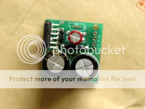
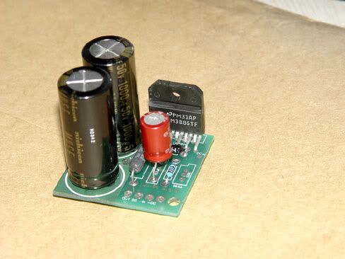
Revised repeatedly,optimization...I finished this PCB project at last.Thanks for 1audio, carlmart, jcarr very much.please look at the primitive scratch for more detail 😀
😀


I have set up some 'leap' points on pcb, it is joined that it is convenient to expand.bridge or parallel is easy.
yours
-digi
😀
I have set up some 'leap' points on pcb, it is joined that it is convenient to expand.bridge or parallel is easy.
yours
-digi
digi01 said:Revised repeatedly,optimization...I finished this PCB project at last.Thanks for 1audio, carlmart, jcarr very much.
I have set up some 'leap' points on pcb, it is joined that it is convenient to expand.bridge or parallel is easy.
The pcb looks very, very good. Just three things, some mentioned on one previous mail of mine:
1) The tracks to +V and -V should be wider. If the pins are N/C, as the data specifies, you can use that area to make the track wider, on the top or bottom.
2) Provide some area on the bottom to use an SMD output resistor, like the Dale type that Rowland uses.
3) You should bypass the mute pin to ground, like the datasheet specifies. I didn't use it on my first prototype, but it's provided on my revised pcb.
The rest is very good. Congratulations! Is it possible to get some, paying of course?
Carlos
carlmart,thanks for you helpful suggestions again😉
Pins of LM3886 arranges very inconvenient,when you lay out with fat tracks,those NC pins is really a hell its mute pin and gorund pin let the things become complicated too.
btw,please check you mail😀
digi
Pins of LM3886 arranges very inconvenient,when you lay out with fat tracks,those NC pins is really a hell
its mute pin and gorund pin let the things become complicated too.btw,please check you mail😀
digi
Hi digi-
"for more infor pls mail to vcgft@yahoo.com.cn"
Is this contact handling a "group buy" or outright sales of these boards?
And the boards look great. Only request I have is for a separate mounting hole on the supply capacitor side to suport that end of the board.
Also, are these boards available with the regulartor boards on this post?
http://www.diyaudio.com/forums/showthread.php?s=&threadid=38636
Thanks Troy
digi01 said:carlmart,thanks for you helpful suggestions again😉
Pins of LM3886 arranges very inconvenient,when you lay out with fat tracks,those NC pins is really a hell
Digi01,
We can't get away from some complications when they should be dealt with. The bypass capacitor on the mute pin should be there. Find a way to lay a track on the side, need not be wide, and bypass it to a ground, any ground.
Recently I read on this forum that N/C pins are really so: they are not connected.
If that is so then you can put a pad, solder the N/C pin to it and still put a track or fill over that same area. When I designed my pcb I simply snipped the N/C pins away and used their area for more copper surface.
The -V and +V tracks should definitely be wider, and it shouldn't be hard to do it. I did a single sided pcb for all this, with no wire bypasses, and everything went fine.
Carlos
Hi Troy,I will start another thread for group buy soon.Now, just share with you my DIY precious..hehe...😀
the regulated psu lay out projects is sitll in progress.the board cooperates with my 3886IGC.
Carlos,it is really?Soooooo pretty tidings I will test it.
the regulated psu lay out projects is sitll in progress.the board cooperates with my 3886IGC.
Recently I read on this forum that N/C pins are really so: they are not connected.
Carlos,it is really?Soooooo pretty tidings
I will test it.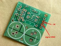
Group buy?
Hey digi01-
The board looks great!
You mentioned earlier a group buy, so I was checking to see about when that was planned, and if I could request the regulator boards be an option in the group buy.
I would "hope" the options would include:
1. PCB LM3886 IGC bare
2. PCB LM3886 IGC + components
3. PCB LM3886 IGC bare + regulator PCB bare
4. PCB LM3886 IGC, regulator PCB + all components
Or if you have a web site, just have each set as an item:
1. PCB LM3886 IGC
2. PCB Regulator
3. PCB Buffer "🙂"
4. Components, LM3886 IGC
5. Components, Regulator PCB
6. Components, Buffer PCB
7. Shipping
Any chance of a buffer circuit being available also? I am planning on paralleling 2-4 of the LM3886's for a more robust output and the buffer would help drive the paralleled inputs.
Thanks again and I look forward to trying them,
Troy
rabstg,thanks for your helpful suggestions.
Sorry for so slow reply.because I am very busy during weekend.
the 3886IGC is available now,it is finished.
the regulator PCB is in progress,may take about 6days available.when finished it,I will start a group order.
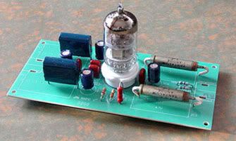
about the buffer circuit,I have a final project.but it is based on the tube,no common indeed😱
I am making a chip buffer project now,it is minimum,double side PCB board,including regulat psu parts.I set up it may be used for paralleling or bridging my 3886IGC.
another,I have lay out a BPA200 PCB board,it is based on the original NS bpa200 article,with DC serv.I wonder anyone interesting it,maybe can go ahead...
glad for your appreciation🙂
yours digi
Sorry for so slow reply.because I am very busy during weekend.
the 3886IGC is available now,it is finished.
the regulator PCB is in progress,may take about 6days available.when finished it,I will start a group order.
about the buffer circuit,I have a final project.but it is based on the tube,no common indeed😱
I am making a chip buffer project now,it is minimum,double side PCB board,including regulat psu parts.I set up it may be used for paralleling or bridging my 3886IGC.
another,I have lay out a BPA200 PCB board,it is based on the original NS bpa200 article,with DC serv.I wonder anyone interesting it,maybe can go ahead...
glad for your appreciation🙂
yours digi
Have you built any prototype or is it only in the computer?digi01 said:another,I have lay out a BPA200 PCB board,it is based on the original NS bpa200 article,with DC serv.I wonder anyone interesting it,maybe can go ahead...
peranders said:
Have you built any prototype or is it only in the computer?
it's only a PCB project,double side board,the size is 149mm x 33mm.I have optmize it again.
Tube buffer
Hello digi,
That tube buffer looks interesting, can you post a schematic? Will you have pcb's available for it ?
/U.
Hello digi,
That tube buffer looks interesting, can you post a schematic? Will you have pcb's available for it ?
/U.
- Status
- Not open for further replies.
- Home
- Amplifiers
- Chip Amps
- my 3886IGC pcb