
I think copper for waveguides is more expensive than aluminum.
For the MDDBL rear acoustic load the spirals can work. The geometry becomes complex if you have to combine 8-12 with lengths up to 2-4 meters.
For the MDDFL front acoustic load I have always used straight waveguides.
For the MDDBL rear acoustic load the spirals can work. The geometry becomes complex if you have to combine 8-12 with lengths up to 2-4 meters.
For the MDDFL front acoustic load I have always used straight waveguides.
I think copper for waveguides is more expensive than aluminum.
For the MDDBL rear acoustic load the spirals can work. The geometry becomes complex if you have to combine 8-12 with lengths up to 2-4 meters.
For the MDDFL front acoustic load I have always used straight waveguides.
I wasn't exactly meaning copper, but the idea of a spiral. (At junkyards, one can find many interesting things.)
Your rear acoustic flexible pipes reminds me of a transmission line. A bunch of flexible tubes can work better than dividing the box speaker with stiff planks to get a longer transmission line. They can even have different lengths, stuffed inside the box and the remaining space filled up with some material to keep the whole thing in place. 🙂
In the frequency domain the MDD technology behaves like the transmission lines and the lowest reproducible frequency can be calculated with the formula F = c / Lmax / 4.
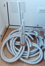
My prototype closest to the proposed idea is the 22C71L8.
The spiral sheaths of the rear acoustic load can be collected inside a box (cubic, cylindrical, ...).
For the frontal acoustic load you can also use: pelanj's project measurement or opt for one of the MDD3FE25 prototype configurations.
My prototype closest to the proposed idea is the 22C71L8.
The spiral sheaths of the rear acoustic load can be collected inside a box (cubic, cylindrical, ...).
For the frontal acoustic load you can also use: pelanj's project measurement or opt for one of the MDD3FE25 prototype configurations.
Attachments
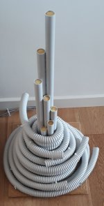
The spiral sheaths of the rear acoustic load can be collected inside a box (cubic, cylindrical, ...).
What type of sound comes out of the rear flexible pipes? Are they more on the low side?
In the 22C71L8 design the rear tubes emit low and mids. Bringing the ear closer to the single tube the sound is characterized by the presence of resonances and not suitable for listening to music. The eight rear and seven front waveguides compensate for the individual resonances to each other, the sound becomes very good.
From the front pipes all frequencies always come out with the individual resonances in relation to the length of the pipes.
The ease in recognizing sounds also derives from the multiple delays of the omnidirectional emission points distributed in 3D space.
From the front pipes all frequencies always come out with the individual resonances in relation to the length of the pipes.
The ease in recognizing sounds also derives from the multiple delays of the omnidirectional emission points distributed in 3D space.
Attachments
In the 22C71L8 design the rear tubes emit low and mids. Bringing the ear closer to the single tube the sound is characterized by the presence of resonances and not suitable for listening to music. The eight rear and seven front waveguides compensate for the individual resonances to each other, the sound becomes very good.
From the front pipes all frequencies always come out with the individual resonances in relation to the length of the pipes.
The ease in recognizing sounds also derives from the multiple delays of the omnidirectional emission points distributed in 3D space.
I think, if the back tubes are stuffed with sound absorbent material, the resulting sound emitted from all the rear pipes together would give good bass sound. Sound waves are longer than the unequal internal surface of those back tubes, so you can get nice bass sound, if you bring all ends of the tubes to one surface, and one hole, flat or round. And, if you won't allow them to jump around.
Last edited:
I agree on fixing the waveguides well to avoid lateral vibrations.
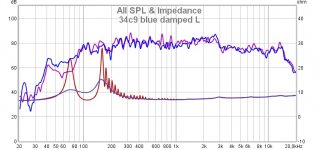
The function of the foam cube can be seen well in the impedance graph found on my 34C9 project. Without damping the impedance peaks, separated by 1/7 octave are visible, red line. With a minimum of damping the bells widen and the impedance trend becomes regular, blue line.
I think that by further increasing the amount of damping material, the emission is too attenuated, reducing the efficiency of the system.
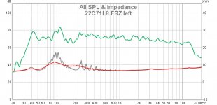
I am also attaching the impedance graph measured in project 22C71L8. Gray line without damping material, red line with a foam cube.
To appreciate the effect of the delayed sound waves of MDD technology, it is preferable to distribute the exit holes in three dimensions. Even with holes spaced in one line, better results are obtained than with holes close together.
The function of the foam cube can be seen well in the impedance graph found on my 34C9 project. Without damping the impedance peaks, separated by 1/7 octave are visible, red line. With a minimum of damping the bells widen and the impedance trend becomes regular, blue line.
I think that by further increasing the amount of damping material, the emission is too attenuated, reducing the efficiency of the system.
I am also attaching the impedance graph measured in project 22C71L8. Gray line without damping material, red line with a foam cube.
To appreciate the effect of the delayed sound waves of MDD technology, it is preferable to distribute the exit holes in three dimensions. Even with holes spaced in one line, better results are obtained than with holes close together.
Attachments
I am only speaking about dampening the rear flexible tubes. They are transmission lines, whatever their different lengths. If you take all the ends of the rear tubes and ties them in one plane, it'd give a quite good low frequency sound, you'd get good bass. For example, put all the ends of the rear tubes in a bigger piece of a round tube or a box. That end would be like a end of a horn. Sound doesn't choose, where to go, it goes where it finds a free element to move through.
Of course, the rear flexible tubes would start rattling, if you make the sound volume high. So, they have to be tightly held and damped around them too. All told, you hear the sum result of the sound coming out of the ends of the vertical tubes and from the ends of the rear flexible tubes.
I am not talking about the measurements, but you as the subjective listener.
Two details that I forgot to mention in my previous post.
1 - The damping effect of the foam cube at the output of the waveguides is easily seen in the impedance graph but to me it is almost undetectable on listening.
In reverse.
2 - I do not know standard measures to detect the effect of delayed signals of the MDD technology but I am convinced that they are easily perceptible when listening. The quality of reproduction improves by moving the output holes away from each other.
This replica 34C9 by pelanj with Lmax = 2 Lmin = 1000 mm already allows to perceive the effects of MDD technology. The small size penalizes playback below 80Hz. The simplest solution is to add a sub.
Stretching the waveguides improves bass reproduction and reinforces the MDD effect. In this case the construction becomes more complicated and even the aesthetics worsen.
The quality of reproduction improves by moving the output holes away from each other.
Stretching the waveguides improves bass reproduction and reinforces the MDD effect.
Very interesting info. Thank you!
This is an interesting concept, sorry that I missed this post when it was new.
The omni effect is surprising, because I've seen this done in reverse and the point was to make a vey directional shotgun mic. My uncle built one back in the 60s, he probably still has it. I tested it, it was indeed directional. See the image below and here is a link to a recent build.
https://cdn.preterhuman.net/texts/g...ourcedns.com/_gbpprorg/mil/shotgun/index.html
If the speaker is omni, is that coming from the gap at the bottom, or out of the tubes?
I think Claudio (claudiogan) could explain better, but I imagine that when the sound goes through the tube, it is diffracted at its end. I have really not much understanding how it works beyond loading at LF. DonVK made a simulation of the smaller version, so I think it all would scale up: https://www.diyaudio.com/community/...ional-single-drive.342677/page-5#post-6198181
When the sound goes out, the diffraction make it omni. When the sound goes in (microphone case), the sound that is not aligned enters the tubes angled. It will get to the microphone itself only through reflections (and each reflection dissipates energy), making anything that is not aligned (direct sound wave passing through the tubes with minimal reflections) attenuated. That was my understanding on the physics behind a speaker and a microphone using this concept.
It's correct. For those who want to explore similarities and differences with microphones:
https://www.diyaudio.com/community/...tl-omnidirectional-single-drive.342677/page-3https://www.diyaudio.com/community/...tl-omnidirectional-single-drive.342677/page-4
https://www.diyaudio.com/community/...tl-omnidirectional-single-drive.342677/page-3https://www.diyaudio.com/community/...tl-omnidirectional-single-drive.342677/page-4
1) The omnidirectional emission mechanism of MDD technology is based on acoustic diffraction. It is described correctly in many posts on the diyaudio.com forum.I think Claudio (claudiogan) could explain better, but I imagine that when the sound goes through the tube, it is diffracted at its end. I have really not much understanding how it works beyond loading at LF. DonVK made a simulation of the smaller version, so I think it all would scale up: https://www.diyaudio.com/community/...ional-single-drive.342677/page-5#post-6198181
2) To understand how the low frequency response works, you need to remember:
a) how to calculate the resonances of a waveguide open only on one side (the first is f = c / L / 4)
b) how to calculate the resonances of a waveguide open on both sides (the first is f = c / L / 2)
The rear compression chamber and multiple guides activate both types of resonance by creating a series of peaks in response that compensate for each other and making the MDD cabinet neutral with respect to the TS parameters of the driver.
In the latest MDD3ZZ350 project with Lmax = 2 Lmin = 3400 mm there is a first frequency of type a) of the waveguide at about 25 Hz, the following ones covering the entire first octave homogeneously. The first resonance of type b) is at about 50 Hz, the following ones cover the entire second octave in a homogeneous way.
In other words: even for the frequencies of the first octaves there is an optimal path to transfer the sound energy from the rear side of the drive to the listening environment.
These are theoretical values as the 3FE25 driver (excellent!) cannot reproduce the 25 Hz. A second limit of the driver is certainly the maximum SPL. Listening you can follow the bass lines well up to 40 Hz with about 90 dB in room.
For further information:
https://www.claudiogandolfi.it/mdd3fe25.html#dhttps://www.claudiogandolfi.it/acustica.html#neutral
3) A third aspect of MDD technology, for me the most important and innovative, is the emission of coherent and delayed secondary sound fronts. There are no standard measures of these parameters, for now I know the existence of only two MDD replicas. Now my further insights would remain reflections for myself.
Last edited:
- Home
- Loudspeakers
- Full Range
- My 34c9 (omnidirectional full range with 3FE22) build