I hope they will sound as good as the first version - all in all, there were only cosmetic changes. I use a bit of EQ on both ends when listening at lower levels and a subwoofer when listening at higher levels. The sound is different to anything I have heard before. They are omnidirectional, the sound does change only very little when you move around the room if you keep the head at the same height. I mentioned the 2D/3D effect somewhere in this thread. The instruments stay in their places - always in the same relation to the towers - left to right and front to back. I would say very impressive for two little fullrange speakers. The only drawback I see is the limited maximum SPL - definitely not for large rooms.
Few questions;
1) Why should the speaker has to hang few cms above the floor? Is it because the sound goes out from the back of the speaker, hits the floor and spread out from it?
2) If that's so, can't half lengths of the pipes added to the top and the bottom, and leave the speaker hang higher? (Half from the lengths you used?
Thanks
Claudiogan would explain better - but the lenght of the tubes is not important only for the height, but also for loading the front of the speaker. Splitting the tubes in half would not provide the required loading.
And the back of the speaker is close to the floor to provide bass reinforcement from the floor.
It is also possible to load both sides of the speaker - you can see the options in Claudiogan's original thread: https://www.diyaudio.com/forums/pla...nidirectional-single-drive-5.html#post6017746
And the back of the speaker is close to the floor to provide bass reinforcement from the floor.
It is also possible to load both sides of the speaker - you can see the options in Claudiogan's original thread: https://www.diyaudio.com/forums/pla...nidirectional-single-drive-5.html#post6017746
OK, I'll ask @claudiogan too. Hope, he reads this thread an reply. 🙂
If it is a question of bass from the floor, the speaker could be enclosed in an additional tube on the bottom. The distance between the bottom of the tube and the floor could be 10mm.
Also, if you are using a full range speaker, the bass rage also goes out of the tubes, so won't bass be heard from top of the tube (I suppose the lowest tubes)?
If you place a subwoofer 1 m above floor vs on the floor, you will notice a difference, that is what I meant - in theory, there is some gain from the boundary. I use a subwoofer with these anyway and I like the looks of the towers (now sprayed black), so I never thought about changing the arrangement.
MDD
MDD projects (thread) have a multiple waveguide structure to generate omnidirectional and delayed sound wavefronts at different points in space. For the Haas effect it is possible to distinguish two sounds if delayed between 5 and 40 milliseconds (depends on the complexity of the sound). With one meter in length, delays of up to 3 milliseconds are generated, with 2 meters delays of up to 6 milliseconds are generated. Delayed signals reduce the possibility that in the envelope of the sound heard there are time intervals with zero or very low acoustic energy. With evenly distributed delayed signals it is easier to recognize sounds. In the presence of reflections of the environment separated by less than 5 msec, the brain perceives a single sound to be interpreted and not two distinct reflections to be traced back to a single origin.
The pelanj prototype of project 34c9 has only front loading (MDDFL), the maximum length is 1 meter. It generates delays of up to three milliseconds which are sufficient to perceive the unique acoustic characteristics of listening with MDD technology. In the MDD3FE25a-b-c-d prototypes I did tests with increasing acoustic front loading lengths from 300 mm to 1600 mm, my preference goes to the longer prototype MDD3FE25d. In the time domain, reducing the lengths of the waveguides means reducing the range of delays and making the Haas effect perceptible in the reproduced sounds, worsening reproduction.
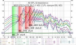
In the frequency domain, multiple waveguides are used in original configurations to optimize the frequency response. As for all TLs, increasing the length increases the response at low frequencies with the L / 4 rule. In the tests carried out by extending the guides over one meter in height, the diffraction emission of the high frequencies was directed above the head of the listener. I solved the problem by applying two acoustic loads to the same speaker. The speaker is positioned at floor level to optimize the emission of high frequencies with the MDDFL front acoustic load with Lmax = 8 Lmin = 1600 mm. The rear emission is sent to the MDDBL rear acoustic load, the series of guides has Lmax = 2 Lmin = 2000 mm to reach 40 Hz. The presence of guides of different lengths creates paths with resonances between 40 and 80 Hz making the cabinet neutral with respect to the frequency response of the speaker.
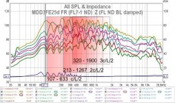
In the pelanj replica Lmax = 2 Lmin = 1 meter and the resonances are between 80 and 160 Hz, the lower frequencies are reproduced with the help of a sub.
The frequency response of the individual waveguides highlights peaks at the L / 4 and L / 2 resonances which compensate each other by covering the entire band emitted by the FR speaker. MDDFL front loading guides output all frequencies, MDDBL rear loading guides only output mids and basses.
Few questions;
1) Why should the speaker has to hang few cms above the floor? Is it because the sound goes out from the back of the speaker, hits the floor and spread out from it?
2) If that's so, can't half lengths of the pipes added to the top and the bottom, and leave the speaker hang higher? (Half from the lengths you used?
Thanks
MDD projects (thread) have a multiple waveguide structure to generate omnidirectional and delayed sound wavefronts at different points in space. For the Haas effect it is possible to distinguish two sounds if delayed between 5 and 40 milliseconds (depends on the complexity of the sound). With one meter in length, delays of up to 3 milliseconds are generated, with 2 meters delays of up to 6 milliseconds are generated. Delayed signals reduce the possibility that in the envelope of the sound heard there are time intervals with zero or very low acoustic energy. With evenly distributed delayed signals it is easier to recognize sounds. In the presence of reflections of the environment separated by less than 5 msec, the brain perceives a single sound to be interpreted and not two distinct reflections to be traced back to a single origin.
The pelanj prototype of project 34c9 has only front loading (MDDFL), the maximum length is 1 meter. It generates delays of up to three milliseconds which are sufficient to perceive the unique acoustic characteristics of listening with MDD technology. In the MDD3FE25a-b-c-d prototypes I did tests with increasing acoustic front loading lengths from 300 mm to 1600 mm, my preference goes to the longer prototype MDD3FE25d. In the time domain, reducing the lengths of the waveguides means reducing the range of delays and making the Haas effect perceptible in the reproduced sounds, worsening reproduction.
In the frequency domain, multiple waveguides are used in original configurations to optimize the frequency response. As for all TLs, increasing the length increases the response at low frequencies with the L / 4 rule. In the tests carried out by extending the guides over one meter in height, the diffraction emission of the high frequencies was directed above the head of the listener. I solved the problem by applying two acoustic loads to the same speaker. The speaker is positioned at floor level to optimize the emission of high frequencies with the MDDFL front acoustic load with Lmax = 8 Lmin = 1600 mm. The rear emission is sent to the MDDBL rear acoustic load, the series of guides has Lmax = 2 Lmin = 2000 mm to reach 40 Hz. The presence of guides of different lengths creates paths with resonances between 40 and 80 Hz making the cabinet neutral with respect to the frequency response of the speaker.
In the pelanj replica Lmax = 2 Lmin = 1 meter and the resonances are between 80 and 160 Hz, the lower frequencies are reproduced with the help of a sub.
The frequency response of the individual waveguides highlights peaks at the L / 4 and L / 2 resonances which compensate each other by covering the entire band emitted by the FR speaker. MDDFL front loading guides output all frequencies, MDDBL rear loading guides only output mids and basses.
Attachments
Last edited:
I am a newcomer to this field. I've been reading lot of threads, before started asking questions. I like your method, Claudio, and Pelanj's creation. How about repeating the top part on the bottom of the speaker, the other way? The speaker would be hung > 1m above the floor. The sound would come from both ends of the tubes. There'd be rigid tubes going up and down from the speaker. Would that maximise the sound? The bottom part of the speaker would also be in a tube as the top is fixed, the smaller 7 tubes would point downwards to the floor, with the longest tube about 10mm above the floor.
The sound would come from different length (height) tubes above your ear and below your ear. Would you try this with your speakers?
(Btw, I don't know Haas, or Schroeder yet.)
The sound would come from different length (height) tubes above your ear and below your ear. Would you try this with your speakers?
(Btw, I don't know Haas, or Schroeder yet.)
Last edited:
It is possible to apply the pelanj acoustic load also on the rear side of the speaker and then suspend everything from the ceiling. The high frequencies are emitted from the front of the speaker and if they are not directed downwards they would be emitted above the listener's head.
I imagine that there would be no great advantages in listening. The range of delays would remain unchanged and all resonances would change little, only a slight decrease for the additional mass of air in the second acoustic load.
In my prototypes I prefer to have Lmax = 2 meters to be able to reproduce even 40 Hz without a sub. I already have some new configurations to make and I can't do the tests you proposed.
The Haas effect is my working hypothesis yet to be demonstrated, I am unable to propose measurements for quantitative detection.
Can you point me to the 2m prototype? Thanks
Also, does the speaker really have to hang above the floor?
Also, does the speaker really have to hang above the floor?
Thanks for the link.
What if I have to use a 6.5" speaker? Can I use a 4Ohm 3-way or 4-way car speaker for this project?
What if I have to use a 6.5" speaker? Can I use a 4Ohm 3-way or 4-way car speaker for this project?
5" full range
Maybe.
I have tested only a 5" driver Ciare HX135 (MDDHX135), The component dimension of pelanj's project is tested only on 3" driver. Total section of waveguide is similar to cone area. If wave guide section is greater you can reduce the omnidirectionality. You can also increase waveguide number. I don't have a ready project, if you want you can try the new configuration with cheap pvc pipes.
I have not done tests with 2-3-4 ways, the crossover and the phase displacements between the drivers could reduce the MDD effect.
Attachments

How do you calculate the logarithmic lengths of the tubes
This post https://www.diyaudio.com/forums/full-range/341739-34c9-mdd-range-speakers-8.html#post5991238.
This post https://www.diyaudio.com/forums/full-range/341739-34c9-mdd-range-speakers-8.html#post5991238.
Maybe.
I have tested only a 5" driver Ciare HX135 (MDDHX135), The component dimension of pelanj's project is tested only on 3" driver. Total section of waveguide is similar to cone area. If wave guide section is greater you can reduce the omnidirectionality. You can also increase waveguide number. I don't have a ready project, if you want you can try the new configuration with cheap pvc pipes.
I have not done tests with 2-3-4 ways, the crossover and the phase displacements between the drivers could reduce the MDD effect.
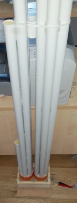
Claudio, are these flexible pipes vibrate by themselves, when you put the volume high? Do they jump around, if you don't tie them together, when the volume is high? Do you have to stuff them with absorbent materials? Thank you.
With the aluminum waveguides used in pelanj's project the volume can be raised to the limit of the power of the 3fe22 / 3fe25 driver.
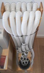
If pvc guides are used, the problem of vibrations exists, pvc pipes are more elastic and can vibrate easily. The circular section makes fixing more difficult. In the MDD3FE25d project I put hot glue dots about every 20 cm. In the prototypes in case of vibrations I add electrician ties or rubber bands. For now, aesthetics are not my problem.
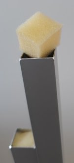
The only damping material used is a foam cube slightly wider than the wave guide. The cube is inserted at the end of the guide and can be easily removed. Protect the driver cone from dust.
If pvc guides are used, the problem of vibrations exists, pvc pipes are more elastic and can vibrate easily. The circular section makes fixing more difficult. In the MDD3FE25d project I put hot glue dots about every 20 cm. In the prototypes in case of vibrations I add electrician ties or rubber bands. For now, aesthetics are not my problem.
The only damping material used is a foam cube slightly wider than the wave guide. The cube is inserted at the end of the guide and can be easily removed. Protect the driver cone from dust.
Attachments
I was asking about the back flexible pvc tubing in the post #52, not the standing ones.
For waveguides in spiral sheath the vibrations are already partially damped by the material. At a high volume it may be necessary to add more tie wraps.
For waveguides in spiral sheath the vibrations are already partially damped by the material. At a high volume it may be necessary to add more tie wraps.
They don't give any resonance?

- Home
- Loudspeakers
- Full Range
- My 34c9 (omnidirectional full range with 3FE22) build