Edit: Or maybe better, learn to use Akabak.
Akabak could do this very easily. Here was something I did with 5 BLH horns.
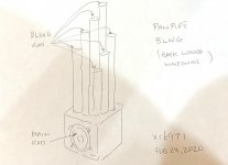
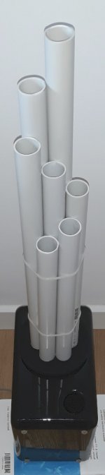
The PANPIPE (Pentahorn) BLH Speaker
The code is basically the same but with the main radiator facing the floor. I am still not sure why one would want the main diaphragm facing the floor. Seems like the driver on this speaker should be flipped around for the smooth open face to direct main sound with treble that likes clear line of sight, and place waveguides up.
Attachments
Last edited:
That looks good. I tried to model 1/9th of a speaker in Hornresp and then add the reponses together. It was not worth the effort really🙂
In the MDD, the main membrane is actually facing the tubes and the tubes are pointed up - and the sound is diffracted at the tube exits.
In the MDD, the main membrane is actually facing the tubes and the tubes are pointed up - and the sound is diffracted at the tube exits.
mdd vs Pentahorn
Premise. The MDD prototypes are characterized by the emission by acoustic diffraction of coherent sound wave fronts and with increasing delays compared to the primary emission of the speaker cone. In this project 34c9 the primary emission is generated from the rear side of the driver. This is an effect to be analyzed in the time domain, I do not exclude given the small number of replicas that I am used to this type of sound. I am aware of two replicas, one is this one made by Pelanj, too few to deepen the discussion on the advantages of coherent and delayed sound waves. My working hypotheses are described in the acoustic page of my site.
The diffraction emission has two important positive effects. Makes the omnidirectional emission horizontally even at high frequencies. It regulates the emission at low frequencies by creating paths with different resonances.
The 34c9 project as in the Pentahorn uses different resonances to regulate the low frequency response.
The 34c9 project unlike the Pentahorn is omnidirectional at high frequencies.
Wanting to simulate the system (I am unable to do it) it is necessary to keep in mind that each waveguide has odd resonances that start from L / 4 as in TL systems. The common volume between the cone and the beginning of the guides simultaneously activates the equal resonances starting from L / 2. In this volume the guides can exchange energy with the other guides side by side, as if the beginning of the guide was outside.
Akabak could do this very easily. Here was something I did with 5 BLH horns.
The PANPIPE (Pentahorn) BLH Speaker
The code is basically the same but with the main radiator facing the floor. I am still not sure why one would want the main diaphragm facing the floor. Seems like the driver on this speaker should be flipped around for the smooth open face to direct main sound with treble that likes clear line of sight, and place waveguides up.
Premise. The MDD prototypes are characterized by the emission by acoustic diffraction of coherent sound wave fronts and with increasing delays compared to the primary emission of the speaker cone. In this project 34c9 the primary emission is generated from the rear side of the driver. This is an effect to be analyzed in the time domain, I do not exclude given the small number of replicas that I am used to this type of sound. I am aware of two replicas, one is this one made by Pelanj, too few to deepen the discussion on the advantages of coherent and delayed sound waves. My working hypotheses are described in the acoustic page of my site.
The diffraction emission has two important positive effects. Makes the omnidirectional emission horizontally even at high frequencies. It regulates the emission at low frequencies by creating paths with different resonances.
The 34c9 project as in the Pentahorn uses different resonances to regulate the low frequency response.
The 34c9 project unlike the Pentahorn is omnidirectional at high frequencies.
Wanting to simulate the system (I am unable to do it) it is necessary to keep in mind that each waveguide has odd resonances that start from L / 4 as in TL systems. The common volume between the cone and the beginning of the guides simultaneously activates the equal resonances starting from L / 2. In this volume the guides can exchange energy with the other guides side by side, as if the beginning of the guide was outside.
Hi Claudiogan,
I would have to place the radiators at their respective (x,y,z) locations and each aiming up to the ceiling. The driver radiator would aim down at the floor (with known) distance. Akabak is unique (in 1-dim lumped codes) in the ability to arbitrarily place radiatiors at any orientation. Limited only by max number of nodes per system of 55. Multiple systems can be combined for more nodes but the systems are independent and do not interact acoustically. But I think 55 nodes is sufficient as each pipe is only 2 nodes and chamber is 1 node, and driver is 2 nodes (2 faces of the membrane). When I have some time, I will do it - but don't have time to read all your descriptions. if you can give me the length and diameter of each pipe, it's height above the floor, and its separation from neighboring pipe, and the distance the main driver is off the floor, and the volume of the main chamber, I think I can simulate it rather quickly. Akabak will account for the spatial separation and location of each pipe's radiator (imaginary membrane made of "air" at the exit plane of each pipe). Then the simulated frequency response and time dependent step and impulse response will be calcuated at the listening position (arbitrary, say 2.5m away at circa 40in above the floor - a typical seated listening position).
I would have to place the radiators at their respective (x,y,z) locations and each aiming up to the ceiling. The driver radiator would aim down at the floor (with known) distance. Akabak is unique (in 1-dim lumped codes) in the ability to arbitrarily place radiatiors at any orientation. Limited only by max number of nodes per system of 55. Multiple systems can be combined for more nodes but the systems are independent and do not interact acoustically. But I think 55 nodes is sufficient as each pipe is only 2 nodes and chamber is 1 node, and driver is 2 nodes (2 faces of the membrane). When I have some time, I will do it - but don't have time to read all your descriptions. if you can give me the length and diameter of each pipe, it's height above the floor, and its separation from neighboring pipe, and the distance the main driver is off the floor, and the volume of the main chamber, I think I can simulate it rather quickly. Akabak will account for the spatial separation and location of each pipe's radiator (imaginary membrane made of "air" at the exit plane of each pipe). Then the simulated frequency response and time dependent step and impulse response will be calcuated at the listening position (arbitrary, say 2.5m away at circa 40in above the floor - a typical seated listening position).
I am not Claudio, but I can provide the description of mine - it should be very close to the original. They are tubes with lengths 540, 583, 630, 680, 735, 794, 857, 926, 1000 mm - the driver is facing up and the edge is 100 mm above floor (so each tube ends length + 108 mm above floor - due to chamber length). My tubes are 20x20 mm with 1.5 mm wall thickness. They are arranged into a spiral and the chamber above the driver is 60 x 60 x 8 mm + cone volume. It would be very interesting to see what Akabak will show.
hi xrk971
for the 22C71L8 project it is not yet time to do a simulation, the exit positions of the guides are not in predetermined points. With each montage, something changes. I am preparing a structure that allows to fix the guides in predefined positions and to change the driver (up to 5 ”) leaving everything else unchanged.
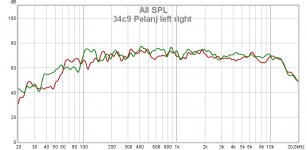
There remains the problem of the interaction of the speakers with the listening environment. In my measurements, even with the mdat file with the measurements made by pelanj on its build with the 3FE22 driver, there are significant differences in the low range between the right and left channel. The attached graph is taken from the file with link in the pelanj post.
The 22C71L8 project can also be mounted with spiral sheaths inside the wall (or on the side). I would like to have an instrument that could automatically detect the characteristics of an environment and suggest an optimal pattern of the position of the outputs of the spiral sheaths. The left and right channel patterns may be different.
for the 22C71L8 project it is not yet time to do a simulation, the exit positions of the guides are not in predetermined points. With each montage, something changes. I am preparing a structure that allows to fix the guides in predefined positions and to change the driver (up to 5 ”) leaving everything else unchanged.
There remains the problem of the interaction of the speakers with the listening environment. In my measurements, even with the mdat file with the measurements made by pelanj on its build with the 3FE22 driver, there are significant differences in the low range between the right and left channel. The attached graph is taken from the file with link in the pelanj post.
The 22C71L8 project can also be mounted with spiral sheaths inside the wall (or on the side). I would like to have an instrument that could automatically detect the characteristics of an environment and suggest an optimal pattern of the position of the outputs of the spiral sheaths. The left and right channel patterns may be different.
Attachments
move to MDD tecnology
Hi hitsware
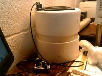
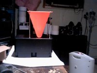
what I see in the photo does not use MDD technology. It can be the basis of an MDD system by adding the guides as in the photo.
The JB3 desk speakers are positioned horizontally, I used the front grill as a support for seven 25mm rigid PVC waveguides. The lengths are: 276, 305, 336, 371, 410, 453, 500 mm.
I have no measures. You can verify that the speaker becomes omnidirectional and check if you perceive the effect of coherent and delayed secondary waves.
Mark II
Hi hitsware
what I see in the photo does not use MDD technology. It can be the basis of an MDD system by adding the guides as in the photo.
The JB3 desk speakers are positioned horizontally, I used the front grill as a support for seven 25mm rigid PVC waveguides. The lengths are: 276, 305, 336, 371, 410, 453, 500 mm.
I have no measures. You can verify that the speaker becomes omnidirectional and check if you perceive the effect of coherent and delayed secondary waves.
Attachments
Last edited:

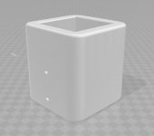
I think I will try to print these new holders. They should look better than my sloppy wooden ones.
Hi Pelanj
looking at the rendering, it is time to go immediately to 3D printing, the appearance is captivating.
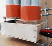
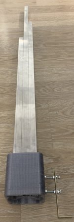
For my prototypes for now it is not worth it, they last too little, a few weeks. I send the photo of one last modification, the compact version of the MDD3FE25c project, the base is reduced from 300 to 180 mm, the sound quality remains unchanged.
The internal volume is a parallelepiped of 45 x 80 x 160 mm with the opening for the speaker and for the rear acoustic load. The change stems from the need to permanently fix the frontal acoustic load, four screws suspend it about 15 mm above the speaker and allow its adjustment. The total volume is about double your latest 3D model.
One thing I don't know about 3D printing is the mechanical strength of the models. As you can see, the bracket with a 2.5 x 25 mm section folds considerably due to the weight of the 1.4 meter high structure. I am waiting to try with waveguides up to 2 meters with a not insignificant weight increase.
Attachments
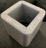
The print out of grey half translucent recycled PET turned out really well. Now I hope it will fit the tubes🙂
Attachments
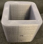

The model needs some adjustments, so the STL will follow after that🙂
Attachments
Last edited:
Nice work pelanjThe model needs some adjustments, so the STL will follow after that🙂
looking at your base I thought of applying 3D printing to the last prototype that I am preparing, I could use two blocks similar to yours connected. One for front loading and one for rear loading.
Some curiosities.
How long does printing take?
Does the base obtained have a resistance equal to or less than wood?
Does the sound change compared to the wooden base?
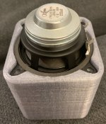
This particular one took slightly less than 5 hours with a 0.5 mm nozzle and 0.4 mm layer height. I have a new model, but yet have to print it. It will make a tighter fit. I made the square intentionally larger by 1 mm, but it was too much. Also, I messed up the driver attachment, so I improved that part as well. I will also use a shorter L bracket with this one.
If you mean resistance like mechanical strength, then this is lighter and more stiff than wood. I am using recycled PET, PETG and PLA would work too I think, I like the rPET material because it seems to be less flexible than PETG, unfortunately it is quite hard to print (needs at least 275 °C hot end temperature, which is close to the limit of my printer) and may be hard to get.
I did not try the sound yet, I will do that when I print the V2.
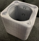
The STL file can be downloaded here: 3D printed audio stuff (with STL files). The pockets are for M5 nuts.
I failed to polish the aluminium tubes perfectly, so now they are getting matte black spray paint. The bases also, so I will end up with a pair of black towers. In my opinion, they look awesome. Will post the result after second layer and mounting together.
I was too lazy to sand the second tower properly and I had some trouble with the spray paint adhering to the surface, I should have used some primer first. Anyway, one tower is finished, I just need to design and print a small enclosure for a speakon female connector, solder some wires and they are back in service again🙂
- Home
- Loudspeakers
- Full Range
- My 34c9 (omnidirectional full range with 3FE22) build