He fredos,
add to that, THOSE are the ONLY IRF530 available in our area.... 2 stores carry SAME mosfets... cant get ANY other makes... MAN!! 😡
im currenly using another mosfet, much faster than IRF530 but lesser in current capacity...aND w/c DOES NOT -POP- when current source IS turned ON...
I hope my trip to cebu city, looking for a bunch of IRF530's, would be fruitful.....
Regards,
Raff
ok... color of cap does not matter eh??(for voltage rating) like grey??
that what is currently in my other board.... .47uF + 41uH (LC filter)
that what is currently in my other board.... .47uF + 41uH (LC filter)
nope. if the voltage is higher than 63V, you can see a number somewhere saying 100, 200, 250, 400 etc. which means teh voltage rating of the cap.
I know since I have a whole boxful of these.
I know since I have a whole boxful of these.
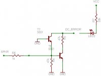
DC protection
heres a -BIT- of the DC protection circuitry found on UCD700 manual.... thanks to HYPEX...
tested by me, although I added 1k(R6) at input because when input is DIRECTLY connected to Vcc or Vee results in: instant DEATH of 2N5551... DC_ERROR pulled to ground when it senses Vcc/Vee.... I added R7/LED2 as visual outputs....
uhmmm might be possibly applicable to OTHER AMPS... 🙂
this circuit should be incorporated in the POWER supply board... w/c its DC_error output is referenced(right term?) to Vcc...... MIGHT? be used as photocoupler to trigger shutdown circuit....
I really dont have any idea as to what/how its connected to the power supply(the DC_error output)....
might be an N.C. relay w/c opens up the supply line GOING to the AMP when fault is detected... etc.. etc....at least thats how I probably think it is...
need your inputs mate.. any ideas/suggestions welcome.. no matter how dumb/silly they are 🙂
Attachments
I don't think the output of the detector has enough drive current to light up an LED.
you can connect the output of the detector to the base of a PNP transistor that will then drive an LED.
you can connect the output of the detector to the base of a PNP transistor that will then drive an LED.
djQUAN said:I don't think the output of the detector has enough drive current to light up an LED.
you can connect the output of the detector to the base of a PNP transistor that will then drive an LED.
try wiring up the said circuit... 🙂 it can light up the LED.. EVEN with supplies of only +/-25V...
now whats the best way to instantly -cutting- power to the AMP??
a NOrmally Closed relay in between filter cap -AND- amp.... is what im thinknig BEST...

DC protect again
for the DC protection.. im thinking about inserting RELAY at the Vcc/Vee lines going to AMP....
-or-
A RELAY in series with the loudspeaker
-or-
MOSFET/s as RELAYS between Vcc/Vee..... <- this one I need to think HOW 🙂
any suggestions welcome....
for the DC protection.. im thinking about inserting RELAY at the Vcc/Vee lines going to AMP....
-or-
A RELAY in series with the loudspeaker
-or-
MOSFET/s as RELAYS between Vcc/Vee..... <- this one I need to think HOW 🙂
any suggestions welcome....
Add fuse to power supply and simply short the speaker output with a Triac. This option will not affect current path with contact and add no lose at all (except fuse lose) to the power amp. If DC is detected, simply short amplifier output to protect load and blow fuse on power supply. DC should never be there, except in case of amplifier faillure. That's the way I protect load on my commercial amplifier.
Fredos
www.d-amp.com
Fredos
www.d-amp.com
wow.. what a bold way to STOP DC at speaker.. 🙂
short OUTPUT of AMP??? more damage done ... 🙁
I think I will go for MOSFETS as switches at outputs of DC supply....
nothing to "destroy" in case DC is/was present in speaker output.. 🙂
btw, I saw PDF datasheet for UCD700 powersupply.. they incorporate relay/s at outputs.....
Im going the "solid state" way... If I succeed...
Normaly, when you got DC at output of an amplifier, damage was already done, ie mosfet are already blow and short. When you short output to ground, you will just blow the power supply fuse and protect a lot much faster the load again damage...
Fredos
www.d-amp.com
PS it's more important to protect load than minimize damage in amplifier...$$$$!
Fredos
www.d-amp.com
PS it's more important to protect load than minimize damage in amplifier...$$$$!
yeah.... DAMAGE to AMP is DONE.. when DC present at speaker output....
MY -gentler- approach would be to just disconnect the power supply lines....
MY -gentler- approach would be to just disconnect the power supply lines....
Out of curiosity is it possible to damage a speaker with only the energy stored in supply capacitance?
RX5
Do you have a drawing of the whole DC protection circuit?
..... like to see other ways of detecting 🙂
I'm using/going to use a circuit published by Douglas Self ... see circuit for full bridge.
Fredos
I like your approach, but it requires fuses in the secondary side of the PSU I guess = nonlinear losses.´
Are you using electronic current protection also, and if so, are the fuses rated well above the electronic current limit (to minimise losses)?
Can you hear any sonic impact of having a Triac on the output (while it's open)?
Attachments
If you put fuse on the AC side of the bridge, or between the bridge and the capacitor, they will have no effect at all on impedance of the supply! Open triac did not change anything in the amplifier performance. I use a fuse between the secondary side rectifier and the bulk inductor, so the effect of the fuse is just a ''bonus'' to the circuit! 🙂. If DC is detected on the speaker terminal (means output fail), triac short, fuse blow and capacitor are discharge trought the triac. In this way, only fews micro second of DC could go to the load (response time of DC protect...), no perver effect of contact or added switch on the power supply...
Fredos
www.d-amp.com
Fredos
www.d-amp.com
Baldin said:RX5
Do you have a drawing of the whole DC protection circuit?
..... like to see other ways of detecting 🙂
I'm using/going to use a circuit published by Douglas Self ... see circuit for full bridge.
Fredos
I like your approach, but it requires fuses in the secondary side of the PSU I guess = nonlinear losses.´
Are you using electronic current protection also, and if so, are the fuses rated well above the electronic current limit (to minimise losses)?
Can you hear any sonic impact of having a Triac on the output (while it's open)?
Here is the link........ I -HAVE- built(very sensitive, turn OFF at high volume settings of my diy UcD, need some more tweaking)..... I ONLY have the 2nd part of the Dc prot..... the MOSFET/s section.... dont have the detector circuit(yet).. I just kinda combined the detection circuitry taken from the UC700 prot scheme....
http://www.diyaudio.com/forums/showthread.php?s=&postid=1070008#post1070008
funny no one posts sensibly there anymore.....
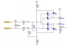
is there a difference detecting betweem classAB and ClassD??
btw, Baldin.. could you post a bigger pic of it?? hard to see 🙂
I just found that it's the same as can be found on ESP 🙂
http://sound.westhost.com/p33-fig1.gif
Can't get any of the interesting links to work, on the thread page you are refering to! ......... so I'm not sure what you ar building ........ but it seems that there might be some interesting threads on SS on the subject 😉
http://sound.westhost.com/p33-fig1.gif
Can't get any of the interesting links to work, on the thread page you are refering to! ......... so I'm not sure what you ar building ........ but it seems that there might be some interesting threads on SS on the subject 😉
- Status
- Not open for further replies.
- Home
- Amplifiers
- Class D
- my 1st ever D-amp, WORKING!!!