Greetings,
I have tried to search for a Moderator and am unsuccessful in doing so; maybe I am not doing something right.
However, if you are a moderator can you please delete: Post #30, Post #31, Post #32, Post #33, Post #34, and Post #35. Thanks in advance.
I have tried to search for a Moderator and am unsuccessful in doing so; maybe I am not doing something right.
However, if you are a moderator can you please delete: Post #30, Post #31, Post #32, Post #33, Post #34, and Post #35. Thanks in advance.
Greetings,
First of all, I like to share my experience with 3DLens.com, I am impressed. I ordered 1 Large Fresnel Lens #F330, 1 Large Fresnel Lens #F550 Thursday the 10th at 10:57:48 EDT, although I paid a bit more for shipping, $27.00. I already got them Sunday morning. Can't ask for a quicker way to get things when they are comming all the way from the other side of the world.
So I finally have something to work with. I have my frame build for my LCD and have the two Fresnel so wanted to setup a test so I can build the frame for the fresnel's. Here is the final numbers I have in mind and some questions.
I entered the following in the calculator:
LCD Size: 19 Inches
Frensel Gap: 1 Inch or 25.4 mm
Frensel FL: 330 mm
Triplet FL: 457 mm (18" x 25.4)
LCD Distance: 546.80 mm
Screen Distance: 9.02
Screen: 100 Inches
I want to take an estimate on placing my front and back fresnel, specially the one on the back (the 330mm one) so I can build the frame accordingly 😉
I see the distance between the LCD and the Fresnel FL is to be approximately 1 Inch or 25.4 mm, but am not sure how far to place the 330 mm Fresnel ?
Thanks in advance.
It states in the guide that """We leave a gap of 15mm between the condenser fresnel lens and the LCD panel and a gap of 20mm between the collector fresnel and the LCD panel."""
gssmind said:Greetings,
I entered the following in the calculator:
LCD Size: 19 Inches
Frensel Gap: 1 Inch or 25.4 mm
Frensel FL: 330 mm
Triplet FL: 457 mm (18" x 25.4)
LCD Distance: 546.80 mm
Screen Distance: 9.02
Screen: 100 Inches
The fresnel F.L. should be 550mm, not 330mm.
Amazing, I had the LCD Distance: 546.80 mm calculated according the 550mm and had made a typing error for Fresnel F.L. value 😉
Also I saw that in the guide but was not sure if it would stand true for me also, so I figured I ask to make sure. Thanks Mikey.
I forgot to ask:
1. What would be a good approximate distance between the bulb and the Tempered glass?
2. What would be a good approximate distance between the Tempered glass and the 330mm Fresnel?
K let me rephrase my question
After reading the guide several times, I am a bit confused and was wondering if someone can point me to the right direction.
According to the guide I got the following:
1. The collimator Fresnel in my case has a rear focal length of 330mm, so I would position the center of the lamp 330mm away, as represented by line X. - THIS PART IS CLEAR.
2. We leave a gap of ~15mm between the condenser Fresnel lens and the LCD panel and a gap of ~20mm between the collector Fresnel and the LCD panel. - THIS PART IS CLARE.
3. Since the Tempered Glass goes in between the collimator Fresnel and the lamp, Is there a good approximate distance between the bulb and the Tempered glass? - I don’t see any approximate distance mentioned in the guide? Or Am I missing something by not interpreting the guide properly?
Design Change
Yesterday I made an attempt to build frame for the Fresnels. Figured I get things ready for the test when I get everything.
Well it turns out that when I measured the distance between the LCD on each side is about 25mm Minimum on both the sides. Pretty much making it impossible to get a distance of 15mm and 20mm from the LCD. One of the reason being my Fresnel Size, its like "FEW mm" on each side over the actual LCD size so it kinda makes it very difficult.
So got kinda 😱 and disassembled the frame. Now the plan is to use all the actual dimentions of the 2 Fresnels, and the LCD and draw out a sketch of box and how the three of them are to be placed with each of them framed individually. Went a looked a at a lot of the PLOGs yesterday and have a pretty good idea, atleast I think.
I will use like Google SketchUp or something to draw it out and then touch post it here to get some idaea and then think about touching the Fresnels and the LCD.
gssmind,
I thought I might put my 2 cents in since you so kindly mentioned my plog on your thread. 🙂
Don't panic about the LCD's wooden frame being too wide. I ran into this problem too. Just thin them out. What I did is make the wooden frame the same width as the metal/plastic frame. This allows you to be as close as about 10 - 15mm to the LCD. This is also why I mounted the back fresnel (the one between the LCD and the bulb) directly onto the LCD frame.
As far as the UV/IR filters are concerned, it matters very little where they are placed. Two things to keep in mind: 1. Too close to the bulb and they will overheat and crack; 2. Make sure all the light that hits the LCD goes through those filters. This second one might be of a concern for you because I think the filters are not as big as a 19" screen. So, if you put them right against the screen, some of the light that hits the screen will be unfiltered. Not good. Also, keep in mind that the glass used for some bulbs already have filters built in. So the extra filters would be redundant. Check my last post on my plog I just made today.
The 18" FL opaque projector lens I used will not have a prayer of focusing the entire 19" LCD. I can't get it to focus the entire 17" screen. My suggestion would be try a 22" or get the Pro Lens.
I do have to agree that this 19" LCD doesn't really provide anything extra beyond a 17" LCD. I actually own that exact Dell 1905 LCD. It's awesome and has a great picture. But, it's only 1280x1024. Although, it does have a good contrast ratio and a good response time. Almost all 17" are 1280x1024. But, if you plan on getting a 19" with more resolution, say 1920x1440, later on then that would be worth it. Otherwise, I would design your projector so that if 19" just doesn't seem to work for you, you can just replace the 19" with a 17".
One other thing that I noticed after I built my projector is light leakage. Not just coming out of the box, but light IN the box that does not pass through the LCD but makes it to the projector lens. Think about it for a sec. You want all the light inside the box to go through the LCD. If it doesn't go through the LCD, it should be blocked. Otherwise, your blacks aren't as deep and your whites get washed out. I suedo fixed this by using black duct tape around the edges of my LCD's frame (the wooden one). Keep light leakage in mind when you build.
Otherwise, things look good! Definitely a good quality job with the frames. Keep it up! Good luck!
It's a few days late, but whatever 😛
I was wondering, since it's just a few mm and your using what? 3/8th ply? would it be possible to try and just router out the extra couple of millimeters and afix the fresnels with a brace? Instead of going through a bunch of extra hooplah. Plus it'd be another way to block ambiant light not needed.
Also, looking at your last set of pics, any plans on painting the inside of your panel frame flat black? I haven't quite reached that point, but it's already in my plans to do so just from reading the other various post and their experiences with a unpainted vs painted surface.
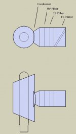
I'll try and make a google sketchup of my lightbox, but basically the light hits an FS mirror before it reaches the fresnel. In that path I have my UV and IR plate glass filters and a couple fans in what I'm hoping will be a kickass reflector! (I used some of that "solar lighting" ductwork to make it) Doing it this way I could keep my filters quite small and hopefully pump out almost all the heat from the light.
I was wondering, since it's just a few mm and your using what? 3/8th ply? would it be possible to try and just router out the extra couple of millimeters and afix the fresnels with a brace? Instead of going through a bunch of extra hooplah. Plus it'd be another way to block ambiant light not needed.
Also, looking at your last set of pics, any plans on painting the inside of your panel frame flat black? I haven't quite reached that point, but it's already in my plans to do so just from reading the other various post and their experiences with a unpainted vs painted surface.
I'll try and make a google sketchup of my lightbox, but basically the light hits an FS mirror before it reaches the fresnel. In that path I have my UV and IR plate glass filters and a couple fans in what I'm hoping will be a kickass reflector! (I used some of that "solar lighting" ductwork to make it) Doing it this way I could keep my filters quite small and hopefully pump out almost all the heat from the light.
Greetings Everyone,
Sorry folks I was very busy this weekend and did not get chance to respond/update the thread.
Bad News
I had disassembled the frame a few days ago and took it out completely. Built a new one and am not as satisfied with it as I keep getting new refined ideas in my head. May be I need to stop having such a vivering mind. But I will stick to this one this time and only change it if its absolutely necessary. I'll test it out with these frames and see some results and if the tuning requires a design change then I'll get to it at that time.
Good News:
I got the 18" E. F. Lens this weekend, so I can do some testing. BTW I got like three of them for future projects 😀 However I don't have the Lamp and the Ballast. But have the Fresnel’s and the LCD mounted in the frame. I would post new pics but am updating my website where I am going to put all the pics permanently so will post it there directly and post a link here.
Also I am going to use the 20x40 as the base, so the plan now is to draw the layout of components and calculations and then will try to aligh the frames on the base (temporarily). However, for me to proceed I need to have a good estimate of how much room is my Ballast and the lap is going to take. I bought the "LL65K T15 Kit" and looked at a lot of pics and PLOGS but am still not sure what would be a good estimate. I was thinking if 5-8 Inch would be good enough....but am not sure. Any suggestions?
I will post a sketch of what I have in mind as a general layout and see what you guys think.
Sorry folks I was very busy this weekend and did not get chance to respond/update the thread.
I already had a 3/4" MDF which I had bought for making a subwoofer enclosure and had the sheet cut into 2 pieces of (20x40) and 2 of (17x40) and more... but did not get a chance to finish making the box. FYI the PJ took Priority 😀 so I figured why not use the same pieces for my PJ. And hence now I am paying for re-using that thick MDF for my PJ frame.I was wondering, since it's just a few mm and your using what? 3/8th ply?
No plans as of yet, but just like you I have not quite reached that point yet so I figured I can wait. Plan is to see how the test-bed results turn out and then go about fine tuning it.Any plans on painting the inside of your panel frame flat black?
Bad News
I had disassembled the frame a few days ago and took it out completely. Built a new one and am not as satisfied with it as I keep getting new refined ideas in my head. May be I need to stop having such a vivering mind. But I will stick to this one this time and only change it if its absolutely necessary. I'll test it out with these frames and see some results and if the tuning requires a design change then I'll get to it at that time.
Good News:
I got the 18" E. F. Lens this weekend, so I can do some testing. BTW I got like three of them for future projects 😀 However I don't have the Lamp and the Ballast. But have the Fresnel’s and the LCD mounted in the frame. I would post new pics but am updating my website where I am going to put all the pics permanently so will post it there directly and post a link here.
Also I am going to use the 20x40 as the base, so the plan now is to draw the layout of components and calculations and then will try to aligh the frames on the base (temporarily). However, for me to proceed I need to have a good estimate of how much room is my Ballast and the lap is going to take. I bought the "LL65K T15 Kit" and looked at a lot of pics and PLOGS but am still not sure what would be a good estimate. I was thinking if 5-8 Inch would be good enough....but am not sure. Any suggestions?
I will post a sketch of what I have in mind as a general layout and see what you guys think.
5-8 inches? hmm you might want to wait and actually get your hands on the bulb before you make your design. I purchased an Ushio 400w MH bulb and ballast for mine and it was alot larger than I was envisioning, even though I knew the measurements beforehand.
Looking at lumenlab's site, they are probably shipping you the exact same bulb that I have. 😛 It's nearly a foot long once you add the mogul base, and the ballast is probably 4"wx6"lx3"h, though I don't think your gonna get the same ballast as me.
Anyhow, I think I'm going to go ahead and order the 19" widescreen fresnels from Lumenlabs once they are back instock and start constructing the enclosure for the lcd, using some lexan and a transparency for the screen till I can get my distance/orientation right.
I forgot to mention that, I ment 5-8" length; that is from back-to-front 😉
Yeah, I would expect it to be about a Foot wide.
[Ballast/Bulb==330mm===>LCD==550mm==>Triplet]
[Distance? ===330mm===>LCD==550mm==>Triplet]
This is kinda funkey way to show this but it does the trick 😀
Yeah, I would expect it to be about a Foot wide.
[Ballast/Bulb==330mm===>LCD==550mm==>Triplet]
[Distance? ===330mm===>LCD==550mm==>Triplet]
This is kinda funkey way to show this but it does the trick 😀
I think I see what your getting at  ,
,
Since the ballast doesn't have to be right next to the bulb, I'd look more at
reflector/bulb->330mm->LCD->550mm->triplet
of which the area of the reflector/bulb can be anything you deem is appropriate to your build. In my build with the lightbox, it ends up being about 5" tall, but the actual source of light is about 3" from the base, so my collumating fresnel should end up being about 16" from the base of my build. Of course I don't plan on totally relying on that measurement, and instead will determine the distance after testing it with the fresnel.
Basically I'm going to try and build mine to where it is the least amount of hassle to upgrade it later.
, Since the ballast doesn't have to be right next to the bulb, I'd look more at
reflector/bulb->330mm->LCD->550mm->triplet
of which the area of the reflector/bulb can be anything you deem is appropriate to your build. In my build with the lightbox, it ends up being about 5" tall, but the actual source of light is about 3" from the base, so my collumating fresnel should end up being about 16" from the base of my build. Of course I don't plan on totally relying on that measurement, and instead will determine the distance after testing it with the fresnel.
Basically I'm going to try and build mine to where it is the least amount of hassle to upgrade it later.
By the way, a while back I mentioned I'd put a sketchup of what I've gotten completed so far. 😛 I fiddled around with it today and produced something almost legible. 
I'm not sure exactly how well it'll work in the end, it looks pretty nice sitting on my shelf though. 😀 There are fans covering both filters and the bulb itself, so hopefully I can keep the whole thing cool enough not to crack the condesor or the filters. The material is made from one of those ceiling mount solar light fixtures and is an almost perfect mirrorred surface, I just hope it stands up to the heat of the bulb. Also, I have yet to see just how much heat the whole thing will remove from the light. The dimensions in the picture aren't to scale of course.
Anyhow, lemme know what yall think. Hope ya'll don't mind me sticking this in this thread, figured since it was brief and we've been talking about such things it was better than starting a whole new one.
Attachments
Greetings,
Here is the sketchup that I made:
Here is the sketchup that I made:
An externally hosted image should be here but it was not working when we last tested it.
Hmmm, in your diagram is that 11 3/4" from the arc to the lcd panel? Would that adequately cover your collumating fresnel? Using google to convert 330mm to inches gives me back 12.99" in distance. Where are the more experienced when you need them eh? 😀
Did you have any plans for UV and IR filters?
Did you have any plans for UV and IR filters?
Thanks for pointing that out Dovienya, I do realize that 330mm = 12.99 Inch.
However, I am sorta sure, sorta unsure of how I am going to place the bulb and the cooling deviecs yet. I will see how much difference it makes with an Inch or since my wood is already cut to 20x40 😉
As far as the cooling goes, I got the Pro Reflector from LL so that should hopefully take care of that 😉 I will only find out the reality by testing it so I'll tweek it as necssary.
- Status
- Not open for further replies.
- Home
- General Interest
- Everything Else
- The Moving Image
- DIY Projectors
- My 19" LCD Projector