Portlandmike said:Make C18 a 0805 if its not already to accomidate Panasonic ECU series.
Also, you might want to add a 1210 pad for the output filter cap C11 if it isn't already. The panasonic ECP series might do well there, and it would be worth a try.
You might also add a Cap pad from the output filter cap to a solder pad for bridge applications;>). Its useful to sync them.
Something like 22nF. Make it big though, 1206, because it sees more volts. A AGND pad might also be nice so you can connect bridge amps via twisted pair. Just a wish, clearly hackable if no space.
C18 uses an 0805 footprint.
The filter cap footprint is one I made for a 5mm lead spacing film cap that also has an 0805 footprint directly between the through holes on the back side of the board (you don't see this on the schematic). The intended use for the 0805 part is a high value loading resistor (>=20k), but you could also populate a 0805 or 1206 size cap there without any modification to the board.
I'll think about adding a part for a bridging/sync cap. There is space for it but it would be just as easy to use an off board leaded cap. That footprint would only need to be 0805 because you can get 22nF ceramics up to 100V X7R and 50V NP0 in 0805 size. No AGND pad is necessary since there are three through hole connections for power supply and output wires. You can just tack onto one of those or the output cap AGND connection.
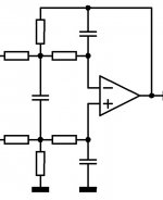
As far as the schematic goes, lumanauw brings up a good point about the feedback configuration. In Bruno's "Simple Self-Oscillating Amplifier with Full Output Filter Control" AES convention paper (May 2005) he shows a diagram similar to what lumanauw posted above. The only difference between that and the one Mike mentions is that the feedback resistor is now connected right in front of the first input resistor. Would this connection be more beneficial? This change would require me to reroute the input section (which isn't really a big deal).
I don't know how this "additional passive pole" should be done properly, but there's 1 other possibility that can be done (besides the 2 possibilities above).
That is to put 2 capacitors, one parrarel to R1 and one parrarel to R2 (?, not so clear) in the schematic in post#297.
What do you think about this possibility, Portlandmike?
That is to put 2 capacitors, one parrarel to R1 and one parrarel to R2 (?, not so clear) in the schematic in post#297.
What do you think about this possibility, Portlandmike?
car amp
Hi Brian,
Do you know anyone willing to build a car amp around your 10w modules ?
Thanks.
Hi Brian,
Do you know anyone willing to build a car amp around your 10w modules ?
Thanks.
Hi vizion.
I don't know of anyone who has or would want to build a car amp around these modules. If I were to use the MP7720 in a car application I would have chosen to configure it to work with a single supply for simplicity. If you're looking for a good, low power car amp check out the Tripath amps based on the TA2020, TA2024, and TA2021B (same chip, different packages). They can run off of a single supply rail (8.5-14V) and have the same output power as the D10.1s because they use bridged outputs.
I don't know of anyone who has or would want to build a car amp around these modules. If I were to use the MP7720 in a car application I would have chosen to configure it to work with a single supply for simplicity. If you're looking for a good, low power car amp check out the Tripath amps based on the TA2020, TA2024, and TA2021B (same chip, different packages). They can run off of a single supply rail (8.5-14V) and have the same output power as the D10.1s because they use bridged outputs.
lumanauw said:Hi, Portlandmike,
Talking about adding another pole to UcD feedback, what do you think about this one? Is this better/worse than the "H" configuration you mentioned above?
I've seen that, and I'm not sure if its the same. One could analyze it and figure it out but I'm a bit short on time now.
All I can say is I know what I told brian to do works and has good benifits.
It basically does two things.
It rolls off the input from any high frequency trash an extra 6dB per octave, which is always fine, but it also decreases the magnitude of the oscillation sine wave on the output, hence, increasing the negative feedback if you've read the mentioned AES paper.
Its not required in the design Bruno shows at the end as the "UCD" example, because he's already running decently high gain, and rightly so with a high power amp.
I brought up this option because I ran into a similar problem were I didn't really want much gain in the ucd because I'd rather drive it with a big signal from the op amp in front of it.
Brain, If its a hassel, just go with what I gave you.
Frankly, unless someone puts up a hand for the other circuit who understands how to use it then it might not be worth it.
Best Regards,
Mike
Hi, Portlandmike,
Thanks for the explenation 😀 I also think that your "H" network is better.
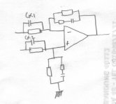
Just wondering. Can this Cx1 and Cx2 be used to give additional pole besides the "H" configuration?
oops, sorry, from output to feedback point there should be L-C drawn.
Thanks for the explenation 😀 I also think that your "H" network is better.
Just wondering. Can this Cx1 and Cx2 be used to give additional pole besides the "H" configuration?
oops, sorry, from output to feedback point there should be L-C drawn.
Attachments
lumanauw said:Hi, Portlandmike,
Thanks for the explenation 😀 I also think that your "H" network is better.
Just wondering. Can this Cx1 and Cx2 be used to give additional pole besides the "H" configuration?
oops, sorry, from output to feedback point there should be L-C drawn.
I don't know if the "H" network works better or not. I haven't got my head around Bruno's other network.
Bruno is brilliant though, and I guess it has serious merit.
Like anything, if you don't understand it enough to calculate values, its of little use.
I think your proposed circuit would have serious issues.
The attenuation of the sinusoidal that the ucd operate from would be very attenuated I think.
Also, your adding a zero, not a pole.
If you want to add a zero, do it in the op amp ahead.
For example, in brian's proposed IA front end, ala hypex ucd, add an series RC accross the inverting inputs of the op amp.
I personally would leave filter shaping to the crossover or another op amp stage though.
Regards,
Mike
Hi, Portlandmike,
This means both the H configuration and #308 proposal is doing the opposite (lowering the loop gain) instead of rising the loop gain (lowering the residual sinusoidal).
I think you are right. I just experimented with H configuration and Cx1-Cx2 like in post#308. Both are not reducing the residual sinusoidal, but expand the magnitude of the residual sinusoidal.Also, your adding a zero, not a pole.
This means both the H configuration and #308 proposal is doing the opposite (lowering the loop gain) instead of rising the loop gain (lowering the residual sinusoidal).
Sure he is 😀 I just can't guess yet what he uses for additional pole. I can guess it's rather simple (one or two resistor/capacitor) but how?Bruno is brilliant though, and I guess it has serious merit.
Are you sure about "this means".lumanauw said:Hi, Portlandmike,
I think you are right. I just experimented with H configuration and Cx1-Cx2 like in post#308. Both are not reducing the residual sinusoidal, but expand the magnitude of the residual sinusoidal.
This means both the H configuration and #308 proposal is doing the opposite (lowering the loop gain) instead of rising the loop gain (lowering the residual sinusoidal).
What were the values of your circuit and how did you measure loop gain?
Does making the residual bigger make it lower loop gain?
Is it that simple or does it also matter what it does to the input?
I recall it being fairly into it and not looking at it that way, focusing more on the bode.
If it is indeed correct its a useful insight, thanks.
I do have a working balanced bridged UCD running at a gain less than 2. AT the time of the design, I conclude it was a very good thing (the Hcap). In fact I believe it is soemwhat necessary for a low gain UcD but I can't find my reasoning right now.
I recall that you want to look at the feedback network looking from the output back to the input. If the input R's are really high, the residule at the comparator inputs is already high, and the series RC does little. (say for a gain of one, the most you could raise the residule would be by 2! That's not enough of a zero (looking from output to comparator input) to do much good and results in a low switching frequency re the LC resonance and thus low negative feedback!
Adding the H and say breaking a 10k input cap to a 9k and 1k and adding the "H" cap..... I think you get the idea.
Why run low gain. Well, there can be more than one reason, but clearly a classic one is that a typical diff amp (like the one following a IA front end) has better CMRR. If you look at LM4562's or almost any op amp, you will see that they have a sweet spot for THD that is rarely 2VRMS.
I did the design some time ago, but I believe the loop gain was quite high. I know one concern was actually having enough residual at the time. If you go off doing sim designs, you will find that in reality, comparators need overdrive. I made sure I had at least 20mV. In fact I just check that tonight.
How did you measure loop gain?
Mike
Brono's extra pole as in post #302 is cool!
I see it now.
But.... Brain, the MPS7720 has 20mV of hysteresis, so its benifit is is not useful in your circuit.
Unless of coarse you've got room for another dual op amp ;>)
Good Night!
Mike
I see it now.
But.... Brain, the MPS7720 has 20mV of hysteresis, so its benifit is is not useful in your circuit.
Unless of coarse you've got room for another dual op amp ;>)
Good Night!
Mike
Hi, Portlandmike,
Thanks for the explenation 😀 I will read it more carefully.
Thanks for the explenation 😀 I will read it more carefully.
Is it as simple as Vsquare/Vresidual? Or it need more complex measurement?how did you measure loop gain
Ya, that is my perception. Is it wrong?Does making the residual bigger make it lower loop gain?
Hi, BWRX,
I googled and found there are some coil manufacturer that makes coils for "digital audio LPF". Is this intended for pursuing good SQ or just making space effective coils?
http://www.deltron-components.de/online_kataloge/toko/products/ctlg/coils/digital_amp.html
http://www.deltron-components.de/online_kataloge/toko/products/new/inductors/da1364sb.html
http://www.ctparts.com/powerinductordigitalamp.asp
http://www.coil-master.com/main_pop/Digital_Amp/SR4P_Amp.htm
http://www.coiltrans.com/plus06/img/data/EPS Catalogue.pdf
http://www.fdk.co.jp/cyber-e/coil/trn_cho_cd-c-0506wa.htm
where do you..
Brian;
where did you purchase the MP7720 or any of its siblings?
Checking the manufacturer's web site, they direct you to a distributor, which requires a minimum 100 pc order.
And none of the usual mail-order sellers has it.
Brian;
where did you purchase the MP7720 or any of its siblings?
Checking the manufacturer's web site, they direct you to a distributor, which requires a minimum 100 pc order.
And none of the usual mail-order sellers has it.
I ordered 50 back in July of last year from Avnet for $2.08 each. The price actually went down since then and Avnet still appears have a minimum buy quantity of one so you should be able to buy some in small quantities.
Thanks Brian, I checked with Avnet, and indeed, I can purchase a quantity of one.
I've read the extensive post related to your circuit, but I must confess that I'll have to read it twice to fully digest the amount of information presented here.
Hopefully, one day I will contribute a meaningful post myself.
I've read the extensive post related to your circuit, but I must confess that I'll have to read it twice to fully digest the amount of information presented here.
Hopefully, one day I will contribute a meaningful post myself.
fernando_g said:I must confess that I'll have to read it twice to fully digest the amount of information presented here.
The circuit itself is rather simple; fully understanding how it works is the kicker. I'm still working on that one too 😉
I'm a switchmode power supply designer in my daytime job, and from what I can see, this class-D topology is similar to either the hysteretic topologies or the constant-off time, variable-on time ones.
Both are self-oscillating, variable frequency circuits.
Of course, I'm saying this without the benefit of having built up a circuit, or actually probing the waveforms with a scope.
I may be dead wrong.
Both are self-oscillating, variable frequency circuits.
Of course, I'm saying this without the benefit of having built up a circuit, or actually probing the waveforms with a scope.
I may be dead wrong.
- Status
- Not open for further replies.
- Home
- Amplifiers
- Class D
- My 10W Mono Single-Ended modules - D10.1