If those chips use the same die then why does the 7731 have a lower recommended voltage rating than the 7722 (18V vs 24V)?
I suppose it's due to thermal problems. While MP7722 is working in stereo SE it would dissipate less power than MP7731 being bridged from the same 24V supply (2x10=20W vs 50W in load, chip dissipates proportionally I presume) Thus the specs for 7731 are limited @18V. And MP7782 is probably improved in this area. Ds for MP7782 says
on the first page, while 7731's does not. Having the exposed pad though 😕 Lotsa mystic hereThermally Enhanced 20-Pin TSSOP Package with Exposed Pad

The 7731 typical application schematic uses one half of the chip for signal inversion and gain and feeds that output back to the input of the other half which also inverts the signal but only has unity gain.
Haven't seen this config. Circuit on p.8 of MP7731 datasheet v1.8 definitely looks symmetrical, and very close to such of MP7782 (p.5 of MP7782 ds v1.2) Only the gain for MP7731 is set to 2x10 while 2x15 set for 7782. Overall the circuits are the same, while giving such different specs. This makes me think what MP7782 is better in SNR too.
McDark said:I suppose it's due to thermal problems.
They should have equal thermal performance if they are the same die in the same package, regardless of cnfiguration. But they don't! This sounds like something only MPS would be able to explain. I'll try to send an email to a local rep.
McDark said:Haven't seen this config. Circuit on p.8 of MP7731 datasheet v1.8 definitely looks symmetrical, and very close to such of MP7782 (p.5 of MP7782 ds v1.2) Only the gain for MP7731 is set to 2x10 while 2x15 set for 7782. Overall the circuits are the same, while giving such different specs. This makes me think what MP7782 is better in SNR too.
Hmm... Apparently they changed typical application circuits. The datasheet I've been looking at is MP7731 v1.6 and it has the daisy chained bridged circuit. You are right that MP7731 v1.8 circuit is the same as the circuit shown in MP7782 v1.2 only with different component values.
This makes me think that one of two things. Either they forgot to update the specs for the MP7731 when they updated the datasheet typical application circuit or the 7731 is not exactly two 7720s on the same die.
You keep saying twice the comparators means twice the noise. Correct me if I'm wrong (I may very well be), but noise isn't additive like that. The input noise is referred to the output times the gain of the amp. In the case of the 7731 v1.6 circuit the output noise of one half is added to the input noise of the other half multiplied by a gain of 1. That's where the 390uVrms noise figure came from. These other circuits use capacitive post filter feedback to feed the signal back to each other's inputs.
Darn! I tried to attach the 7731 v1.6pdf but it's to big. I need to see if I can compress or remove a couple pages.
It's my turn to say "hmm..." 🙂 If they really didn't update the specs for different circuit this was what lead me to misunderstanding. But we are still getting closer to truth this way 🙂
Or maybe MP7782 has less resistance switches really? I do remeber Mike said once it is based on MP8040 which is 100mOhm.
😕 These enigmatic datasheets are driving me crazy
But somehow it's additive, right? I do feel that fully digital inversion makes no noise rather than two comparators each havin its own noise. Not the plain sum, I see. SQR(2)? Do not judge me please, I'm really a digital guy 🙂
They should have equal thermal performance if they are the same die in the same package, regardless of cnfiguration. But they don't!
Or maybe MP7782 has less resistance switches really? I do remeber Mike said once it is based on MP8040 which is 100mOhm.
😕 These enigmatic datasheets are driving me crazy
You keep saying twice the comparators means twice the noise. Correct me if I'm wrong (I may very well be), but noise isn't additive like that.
But somehow it's additive, right? I do feel that fully digital inversion makes no noise rather than two comparators each havin its own noise. Not the plain sum, I see. SQR(2)?
Do not judge me please, I'm really a digital guy 🙂BWRX said:Hi McDark. I am reading them carefully.
We are in agreement here.
If those chips use the same die then why does the 7731 have a lower recommended voltage rating than the 7722 (18V vs 24V)?
Sometimes in the semiconductor biz, you will rename a part and give a differnt data sheet to minimize the affect on the mother part. Its done all the time and I could give half a dozen examples.
Maybe this is it, I won't say.
Directly.Mike, where did you get this information from - directly from MPS, a distributor/representative, or did you somehow come to that conclusion on your own?
If your deadset on the Hysteretic mode, then there are better ways to do a bridge. I recall one of there demo boards doing a bridge where both half the circuits were identicle. Like a 4 resistor diff amp, only feedback from both sides. (confusing). The circuit delt with the possiblilty of getting different switching frequencies by positive feedback via some caps. I think it was from the switch node, but maybe the output.I prematurely/incorrectly judged the 7731 based on poor specs without realizing the specs were the result of the circuit topology. The 7731 typical application schematic uses one half of the chip for signal inversion and gain and feeds that output back to the input of the other half which also inverts the signal but only has unity gain. No wonder this has much higher noise than the other configurations... Having realized this, I see that you guys are correct in stating that the 7731 is basically two 7720s on the same die BUT possibly with some sort of limitation because it has a reduced recommended supply voltage range.
Now is you used an outboard comparator ;>) then you could simple hook up the two sets of inputs out of phase and the problem is solved. Also, good bye hysteresis, which if you used a self oscillating post feedback, would maximize negative feedback, and the additional delay of the comparator is compensated for by the extra delay one gets from hysteresis.
I think the demo board is likely a better source for the best circuit topologies in this instance. They use to be downloadable, but they changed the website I think.
Mike
McDark said:These enigmatic datasheets are driving me crazy
Likewise
 It would be nice to hear some real answers from MPS about their "extensive" line of class d chips 😉
Do not judge me please, I'm really a digital guy 🙂
No judging going on here. I'm grateful that you and Mike are participating in the conversation.
Yes, the noise is additive but not directly. I honestly can't remember but you're right that there are some square roots in there somewhere.
Portlandmike said:Sometimes in the semiconductor biz, you will rename a part and give a differnt data sheet to minimize the affect on the mother part.
Of course. But MPS only has 4 offerings, and it seems that 3 of them are basically the same thing! That's definitely strange as I'm sure none of these parts are extremely high volume. They could easily have 2 offerings replace the 4 they have now. Maybe they just want to make their product line appear larger than it is? Who knows.
Portlandmike said:If your deadset on the Hysteretic mode, then there are better ways to do a bridge.
I'm not deadset on hysteretic or phase shift topologies, or single-ended or bridged for that matter. On paper it's easy to see the clear advantages of post filter feedback and bridging. I like the simplicity and lower parts count of the single-ended configuration. Supply rail pumping isn't an issue if you use enough supply capacitance, which most of us do because we can.
In the real world there are audible differences. I only heard an actual UcD module through a cheap speaker before I inadvertently shorted the output and fried some components, so I don't really know what post filter feedback sounds like. I do know that the configuration MPS recommends (configured to use split rail supplies) sounds pretty darn good with the MP7720.
Speaking of post filter feedback, I removed some parts from my boards and cleaned and prepped it for surgery. I should get a chance to do that tonight and fire it up (hopefully not literally) to see what happens.
Portlandmike said:Now is you used an outboard comparator ;>) then you could simple hook up the two sets of inputs out of phase and the problem is solved.
There is no problem to solve if you use a single-ended mono configuration 😉
BWRX said:
Of course. But MPS only has 4 offerings, and it seems that 3 of them are basically the same thing! That's definitely strange as I'm sure none of these parts are extremely high volume. They could easily have 2 offerings replace the 4 they have now. Maybe they just want to make their product line appear larger than it is? Who knows.
never try to understand a marketing type!
Unless of coarse, your attempting to regulate it and can only source current!Supply rail pumping isn't an issue if you use enough supply capacitance, which most of us do because we can.
I've listened much to the MP7720. Both single supply and split rails. The UCD I listen to are Hypex UCD 400's. There is no comparason in price or performance. These are two different leages.In the real world there are audible differences. I only heard an actual UcD module through a cheap speaker before I inadvertently shorted the output and fried some components, so I don't really know what post filter feedback sounds like. I do know that the configuration MPS recommends (configured to use split rail supplies) sounds pretty darn good with the MP7720.
The MPS 7720 is nice sounding, provided you don't over drive it.
I've also measured the 7720 and spent a fair portion of my life optimizing it. It only goes so far. Had I known about UCD back then, I would have been all over it. That's what got me to post here is that I'd assumed someone had done it, because the 7720 is an excellent half bridge, and two make an excellent full bridge.
Adding a comparator is easy, and making it bridged is very simple and only requires one more inductor,7720, and you don't actually even need another output cap because you can just couple between the inductors, but its good practice to put some to ground for RF issues.
Best of Luck and I look forward to hearing about your hearing results! Hope your using a comparator! ;>)Speaking of post filter feedback, I removed some parts from my boards and cleaned and prepped it for surgery. I should get a chance to do that tonight and fire it up (hopefully not literally) to see what happens.
Except for you have hysteresis, and that topology has monotonically increasing distortion above about 1kHz, where as a properly desgined UCD will likely be 20dB lower distortion at 1k and flat accross the audio band (so like 30dB or more db better at 10k.) Otherwise, yeah, you don't need a comparator! ;>)There is no problem to solve if you use a single-ended mono configuration 😉
Mike
Mike,
there's a problem with input caps - presuming you have MP8040 and ext comparator. MP's input is TTL referred to negative supply which is also ground. How do you intend to connect comparator? You will probably need real negative supply (say, -5V) and +5V from MP used for comparator . Or +-12V supply for MP, comparator referred to 0V and level shifting on output. That's not that simple configuration. Hmm... Maybe open emitter comparator? Or you should live with the caps.
I think another option to avoid hysteresis would be diff amp in front of e.g. bridged MP7782 powered from +-12V rails and negative input tied to 0V (it would be input ground). At least there's no DC issues and no hysteresis. But also not that simple and cheap.
How do you think, what was the reason of putting hysteresis in their ICs if it would be so much better without it?
McDark said:Mike,
there's a problem with input caps - presuming you have MP8040 and ext comparator. MP's input is TTL referred to negative supply which is also ground. How do you intend to connect comparator? You will probably need real negative supply (say, -5V) and +5V from MP used for comparator . Or +-12V supply for MP, comparator referred to 0V and level shifting on output. That's not that simple configuration. Hmm... Maybe open emitter comparator? Or you should live with the caps.
I think another option to avoid hysteresis would be diff amp in front of e.g. bridged MP7782 powered from +-12V rails and negative input tied to 0V (it would be input ground). At least there's no DC issues and no hysteresis. But also not that simple and cheap.
How do you think, what was the reason of putting hysteresis in their ICs if it would be so much better without it?
I'm not so sure having the comparator referenced to the negative rail is any big deal, but your right. Not true with the 7720 based parts. With a bridge amp, you don't really care if the output are sitting at say 12V off ground. The inputs, are not an issue either, unless you want to run at very low gain.
You only need one supply and it only need be positive.
This assumes your driving it with a bipolar signal.
But if then you want to buffer the input then you need to center the signal rather low, like somewhere between 0 and 5V.
I haven't looked lately, but I though I recalled the 8040 had a 5V rail comming out? I could be mistaken.
MPS put hysteresis in because it was there own novel topology, and at the time, was very good. UCD post feedback hadn't been invented yet. Or at least not made public.
btw, I just did a quick simulation and yeah, you could drive 8040's on a 24V rail and run a comparator at ground and 5V, and provided you do the feedback correctly, you can drive it with bipolar (i.e. +/2V) re gnd. The inputs are a bit close to ground for my tastes (~.5v at the negative peak) but it would work.
AND, not an input cap in sight! One might want to bias them up a bit, but it wouldn't be required.
Incedentally, Any IC is going to be referenced to one of the rails. Op amps don't have ground terminals, and a designer will pick one rail, positive or negative, to make as his "reference" rail.
On the MPS7720's I believe that's the negative rail, so its not a bad idea to connect the comparator to the negative rail, and in fact, might be better than referencing to some arbitrary voltage somewhere in between.
One thing I really like about the 7720's is they have a differential input, and the 8040's do not.
Best Regards,
Portland Mike
Portlandmike said:
btw, I just did a quick simulation and yeah, you could drive 8040's on a 24V rail and run a comparator at ground and 5V, and provided you do the feedback correctly, you can drive it with bipolar (i.e. +/2V) re gnd. The inputs are a bit close to ground for my tastes (~.5v at the negative peak) but it would work.
And use say AD8611 (it works ok with low input afaik) with diff ttl out and two MP8040 bridged... Pretty nice configuration, 3 SOIC-8 are easy enough for diyers, cheap and powerful enough. Or SE for simplicity, cheap comparator, it would not be much complex than 7720 curcuit. This might work, Brian, whaddya think?
Portlandmike said:Unless of coarse, your attempting to regulate it and can only source current!
If the caps are large enough they can easily handle the pumping with minimal rise in voltage. Look at the UcD modules. No one complains about supply pumping with them and they're much higher power.
Portlandmike said:Except for you have hysteresis, and that topology has monotonically increasing distortion above about 1kHz
Yes, there is a peak in distortion in the range of 5kHz to 10kHz. The low power Tripath amps have this same peak and they certainly don't sound bad. Flat distortion through the audio range is exemplary but that rise in distortion isn't terribly degrading (surprisingly) to the overall sound.
McDark said:
And use say AD8611 (it works ok with low input afaik) with diff ttl out and two MP8040 bridged... Pretty nice configuration, 3 SOIC-8 are easy enough for diyers, cheap and powerful enough. Or SE for simplicity, cheap comparator, it would not be much complex than 7720 curcuit. This might work, Brian, whaddya think?
That looks like it would do the job.
input bias current is a bit high so care will need to be taken with that, but its hardly a show stopper.
Might be spendy though. More than the power section I'd suspect.
I think I wouldn't give up on Brian's split supply concepts quite yet though. Perhaps its not very rational, but I like the audio input in the middle! Better said, I don't like running the comparator input so close to the edge of the CMR.
I have no doubt that it would work though, and even worth a try, but I don't know if you really need the extra current as I think even a bridge 7720 will drive 4 ohms pretty well for music.
If I had the extra current, I'd use a smaller inductor and bigger output filter cap (more cost). That reduces dead time induced distortion (The bane of any class D).
If you added a -5V supply, so you'd have a 24V, +5, and -5, then yeah, but that's getting complicated.
PortlandMike
BWRX said:
Yes, there is a peak in distortion in the range of 5kHz to 10kHz. The low power Tripath amps have this same peak and they certainly don't sound bad. Flat distortion through the audio range is exemplary but that rise in distortion isn't terribly degrading (surprisingly) to the overall sound.
Hi BWRX,
Yeah, they don't sound bad.
Not sure if its the lack of rising distortion, the input section using a dual op amp, the "balanced feedback" or what with the Hypex UCD's, but they are far more open and stage better than anything I've heard.
That's my push to get someone to try a UCD topology on one of these cheap and simple chips.
Perhaps I'll hack one of my MPS demo boards and let you guys know, but its months away.
Best Regards,
Portland Mike
McDark said:How do you think, what was the reason of putting hysteresis in their ICs if it would be so much better without it?
Originally posted by Portlandmike
MPS put hysteresis in because it was there own novel topology, and at the time, was very good.
I would have expected cost to be the deciding factor, although it was clearly part of the design too. It woud have been cool if they had given the comparator output a pin to allow the user to add hysteresis instead of giving it a fixed amount.
Portlandmike said:Incedentally, Any IC is going to be referenced to one of the rails... On the MPS7720's I believe that's the negative rail... One thing I really like about the 7720's is they have a differential input
The 7720's circuitry is referenced to the negative rail. The differential input is very nice, and it can accept voltages to within a couple volts of the supplies. The beauty of the 7720 really is the simplicity.
McDark said:And use say AD8611 (it works ok with low input afaik) with diff ttl out and two MP8040 bridged...
I would use a comparator that allows for a higher range of input voltages if you want to go that route. If you want to use a comparator that only works off of 5V, I would use an instrumentation amp with split supplies to buffer the audio signal and reference the output of the instrumentation amp to 2.5V. I've wanted to try this with the Tripath input stages too in order to get rid of the coupling cap. But again, this all increases the complexity of the design...
BWRX said:
I would have expected cost to be the deciding factor, although it was clearly part of the design too. It woud have been cool if they had given the comparator output a pin to allow the user to add hysteresis instead of giving it a fixed amount.
It has nothing to do with cost. They can make the parts with or without hysteresis and early in the design and developement they had some with no hysteresis.
I've ask them for one w/o hysteresis, but its asking alot. The UCD topology is patented and I doubt that MPS needs another patent litigation.
The 7720's circuitry is referenced to the negative rail. The differential input is very nice, and it can accept voltages to within a couple volts of the supplies. The beauty of the 7720 really is the simplicity.
I would use a comparator that allows for a higher range of input voltages if you want to go that route. If you want to use a comparator that only works off of 5V, I would use an instrumentation amp with split supplies to buffer the audio signal and reference the output of the instrumentation amp to 2.5V. I've wanted to try this with the Tripath input stages too in order to get rid of the coupling cap. But again, this all increases the complexity of the design...
I think that would be ideal, a comparator with more CMR, provided the you can find a part.
I think your on the right path with a diff amp op amp in front, IA configuration is better yet, because it takes whats driving it out of the feedback and allows for either single ended or balanced drive. I think there is a way to use the op amp inputs to buffer the comparator inputs, which would be good, since all comparators have rather non-linear inputs (at least fast enough ones know of. Maybe National will do a new precision comparator that's fast with the VIP50 process!
Some care will need to be taken to mind clipping conditions I think. The op amp could go open loop if your not careful.
When you get farther along, I'll aid you in the feedback design if you like. It will have to a bit later though.
If I get a spare hour or two, I'll try to put together a simulation for the thread.
Mike
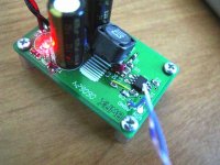
Well, the operation was a success. The MP7720 with post filter feedback works as expected. The parts I used were the closest ones that were on hand. This is a noninverting configuration.
Ri=2k, Rf=20k, Rfl=1.02k, Cfl=220p
Supply rails are regulated +/-12V.
These values result in a switching waveform with a period of about 1.75us, which means the idle switching frequency is about 571kHz. The switching looks just as clean as it did with the MPS recommended circuit on my trusty 10MHz Tek T922.
I only have one channel but it sounds pretty decent out of a Radio Shack 1197 🙂 Now to mod the other board and give the stereo pair a listen.
BWRX said:Well, the operation was a success. The MP7720 with post filter feedback works as expected. The parts I used were the closest ones that were on hand. This is a noninverting configuration.
Ri=2k, Rf=20k, Rfl=1.02k, Cfl=220p
Supply rails are regulated +/-12V.
These values result in a switching waveform with a period of about 1.75us, which means the idle switching frequency is about 571kHz. The switching looks just as clean as it did with the MPS recommended circuit on my trusty 10MHz Tek T922.
I only have one channel but it sounds pretty decent out of a Radio Shack 1197 🙂 Now to mod the other board and give the stereo pair a listen.
Congrates!
Can't wait to hear what you think in stereo.
I just did a sim of 7720 with an op amp in front of it. (Actually two, but I digress) Worked like a champ in simulation and went along way to nullify the hysteresis. (gain of 10, configured like a IA front end driving the comparator inputs directly. Feedback taken into the op amp positive inputs. One for each side. The single channel should be wired as a 4 resistor diff amp too. Connect the ground reference to the speaker output for single ended (The other output for bridge).
Down side is that means you really want a quad op amp so you can do another front end like an IA.
But hey, its only a quad LM4562 and 6 more resistors. I'm sure theres room! ;>)
I simulated a bridge, but that's a non-issue for this config.
Should be smoken good. Your switching frequency lines up very close to what I'd expect. It gets higher if you use an op amp front end to reduce the hysteresis.
Mike
With the MPS circuit I found that I liked the sound better when I set the gain of the amps around -4V/V and used an op amp buffer with a gain of -2V/V in front.
I'd like the switching frequency to be closer to 700kHz, so I'll try to find some suitable caps to replace the 220pF. I suppose I could just put another one in parallel if it comes to that...
I'd like the switching frequency to be closer to 700kHz, so I'll try to find some suitable caps to replace the 220pF. I suppose I could just put another one in parallel if it comes to that...
BWRX said:With the MPS circuit I found that I liked the sound better when I set the gain of the amps around -4V/V and used an op amp buffer with a gain of -2V/V in front.
I'd like the switching frequency to be closer to 700kHz, so I'll try to find some suitable caps to replace the 220pF. I suppose I could just put another one in parallel if it comes to that...
If configured as a UCD, then the hysteresis will also contribute to delay (and more THD too).
If you can muster a gain stage (I recommend a dual op amp and three resistors) the switching frequency will go up.
Might try 2k feedback and 400 ohms between the -inputs. This simulated better than 200ohms, i.e. higher switching freq.
btw, lots of test with the standard circuit showed that 600kHz was pretty much optimal. Not sure if that will hold for UCD feedback though.
The lower distortion benifits of the UCD will be mask to a large degree by the 20mV of hysteresis in the 7720's. There still will be benifits though. Like the switching frequency won't become audible when its near clipping....
I'd have to look at the feedback sim closely to see how much better it would be, but assuming a 10uH inductor and 470nF cap
(feedback resistors alone don't specify a UCD characteristics) I'd guess your taking about a 10dB hit on THD.
Also keep in mind that the Hysteretic feedback your use to varies its switching frequency far more than the UCD. So I personally wouldn't put to much effort into getting it higher. It could even decrease open loop gain.
Mike
The stereo "UcD" pair has been running for a couple days now and sounds very nice. Early impressions are that transients (drums, strings, etc.) are better but the high end seems a bit recessed. This is in comparison to both the MPS circuit and a pair of instrumentation LM3875 amps I've been using.
Noises at turn on are the same but turn off produces a brief squeal with the UcD config. This can be remedied with a different enable circuit. I have this set to disable the chip more quickly on my newer modules but not on the old ones I've turned into mini UcDs.
I need to wind some toroids and replace the surface mount ones currently being using (I was feeling lazy). They had to be tilted so the centerlines of the cores were perpendicular to minimize interaction and noise. That magnetic shieldiing only works so well...
Currently, both modules are configured for a gain of 3 (non-inverting with Rf=4k, Ri=2k). The phase lead components have not changed (R=1k, C=220p) and the switching frequency has only gone down very slightly. The op amp buffer out front has a gain of 2 and drives the non-inverting pin of the MP7720 directly.
I honestly didn't see the switching frequency vary a whole lot with hysteretic feedback and different loads (4 and 8 ohm).
Noises at turn on are the same but turn off produces a brief squeal with the UcD config. This can be remedied with a different enable circuit. I have this set to disable the chip more quickly on my newer modules but not on the old ones I've turned into mini UcDs.
I need to wind some toroids and replace the surface mount ones currently being using (I was feeling lazy). They had to be tilted so the centerlines of the cores were perpendicular to minimize interaction and noise. That magnetic shieldiing only works so well...
Portlandmike said:If you can muster a gain stage (I recommend a dual op amp and three resistors) the switching frequency will go up.
Currently, both modules are configured for a gain of 3 (non-inverting with Rf=4k, Ri=2k). The phase lead components have not changed (R=1k, C=220p) and the switching frequency has only gone down very slightly. The op amp buffer out front has a gain of 2 and drives the non-inverting pin of the MP7720 directly.
Portlandmike said:Also keep in mind that the Hysteretic feedback your use to varies its switching frequency far more than the UCD.
I honestly didn't see the switching frequency vary a whole lot with hysteretic feedback and different loads (4 and 8 ohm).
Attachments
- Status
- Not open for further replies.
- Home
- Amplifiers
- Class D
- My 10W Mono Single-Ended modules - D10.1