BWRX said:The stereo "UcD" pair has been running for a couple days now and sounds very nice. Early impressions are that transients (drums, strings, etc.) are better but the high end seems a bit recessed. This is in comparison to both the MPS circuit and a pair of instrumentation LM3875 amps I've been using.
Currently, both modules are configured for a gain of 3 (non-inverting with Rf=4k, Ri=2k). The phase lead components have not changed (R=1k, C=220p) and the switching frequency has only gone down very slightly. The op amp buffer out front has a gain of 2 and drives the non-inverting pin of the MP7720 directly.
Brian,
Your running very low negative feedback. I doubt your getting even close to the potential. The UCD works better with high gain because the relitive difference of the feedback R's and the input R's form an attenuator and the more attenuation the more loop gain.
Also, with 2k input and 4k Rf, your only getting slight compensation from your 1k+220p.
I know its not intuitive, but making Ri say 1k and Rf 10k will make things sound better. If need be, attenuate the input to accomidate this. Another very very very useful tip is to take your 2k input R and split it to say 1k5 and 390, and add a cap to lower the impedance seen looking back through the feedback network to the inverting input. It also makes an input low pass filter, which is a good thing if not put to low. It keeps Dac trash out, which doesn't help any class D.
Note: its possible that with hysteresis you won't see any difference, but w/o hysteresis it will make a big difference. I'll see if I can look at a sim.
What are you doing to the NI 7720 input?
Is it tied to ground?
What value of inductor are you using?
What filter cap are you using on the output?
I need all those to simulate and optimize.
Thanks for your efforts on this!
Mike
Portlandmike said:I know its not intuitive, but making Ri say 1k and Rf 10k will make things sound better.
I had 2k and 20k and honestly think it sounds better with the 2k and 4k. I reduced the gain so I could drive the input with a higher voltage to reduce the effect of hysteresis (as you mentioned). Plus, isn't it beneficial to shift as much gain as possible to the input stage since the op amps are capable of very low distortion and noise?
Another very very very useful tip is to take your 2k input R and split it to say 1k5 and 390, and add a cap to lower the impedance seen looking back through the feedback network to the inverting input.
I don't understand what you mean here.
What are you doing to the NI 7720 input?
Is it tied to ground?
What value of inductor are you using?
What filter cap are you using on the output?
The modules originally used the inverting hysteresis configuration. I've rewired the modules to a non-inverting UcD configuration. The non-inverting pin is connected to the preamp (which is the low impedance output of an OPA2134).
The inductor is 10uH and the cap is 0.47uF.
Thanks for your efforts on this!
No problem. Any chance you could share your simulation with us? Are you using switchercad?
BWRX said:
I had 2k and 20k and honestly think it sounds better with the 2k and 4k. I reduced the gain so I could drive the input with a higher voltage to reduce the effect of hysteresis (as you mentioned). Plus, isn't it beneficial to shift as much gain as possible to the input stage since the op amps are capable of very low distortion and noise?
I don't understand what you mean here.
The modules originally used the inverting hysteresis configuration. I've rewired the modules to a non-inverting UcD configuration. The non-inverting pin is connected to the preamp (which is the low impedance output of an OPA2134).
The inductor is 10uH and the cap is 0.47uF.
No problem. Any chance you could share your simulation with us? Are you using switchercad?
Brain,
I'll share my simulation. Don't have time right now as I'm working a weekend.
Running gain lower and op amp into the feedback network won't have any affect on the hysteresis affect.
I'll post a couple of sims later with and without.
I'll post the time domain ones. The AC sims for optimizing feedback are far harder to comprehend and play with as you need to understand Bruno's AES paper in detail. Its real easy to come to wrong conclusions if you don't.
the fact that you like it better at lower gains tells me you operating with the hysteresis dominating. I'll sim your way, your circuit maybe better, and then what I think you should try for best results.
Hopefully in the next couple of days.
Enjoy what you got for now. ;>)
Do you have any LM4562's?
Mike
Hi Mike.
Sorry to hear you have to work on such a nice weekend.
Doh! I now realize that the lower gain and the higher voltage input signal has no effect on the hysteresis of the comparator because it isn't inside the feedback loop.
I do have some LM4562s. I'm using them as the differential gain buffer op amps for the instrumentation LM3875 amps. They sound great. The OPA2134 sounds very good in that application too.
I can't wait to see your simulation. Thanks very much for sharing it with us.
LTspice simulations for 7720 with UCD feedback
Hi guys,
I've got two sims for you.
One is Brian's circuit as best as I understand it.
That one is called 7720UCD.
The other is called UCD7720-4562SE
This is more like what it should be.
I don't care to get into UCD education more than this, or LTspice education. I apoligize in advance, I really don't have lots of time right now.
What I will say is that if you look at the node I called "a", and compare it to the rail voltage, this is a measure of the amount of negative feedback. That is, the smaller the peak to peak voltage at node "a" the more negative feedback, or loop gain you have.
More is better in this, argue amonst yourselves if you like.
More than anything, listen.
Also note that in Brian's circuit, it has no filtering of the input. If you connect the square wave source you'll see why I like my method better. Of coarse there is a world of difference and several key features different between the two sims, and you can pick and choose as you like which ones to do.
I suggest a wise man would just the one with the added op amp.
If one is so inclined to make THD estimates from this simulation, don't bother. You could do it, but the 7720 is modeled here as a idealized comparator, and dead time and supply ripple are ignored.
Have Fun, and make good S%$T, not cheap mid fi stuff!
You now have enough to make something decent for DIY'ers.
Portland Mike
Attachments
Hi Mike.
Thanks for the simulation files! Very nice work. The 7720UCD schematic is how I have the amp currently configured.
Either configuration will be cheap and both already sound better than mid fi equipment 😉
Thanks for the simulation files! Very nice work. The 7720UCD schematic is how I have the amp currently configured.
Portlandmike said:Have Fun, and make good S%$T, not cheap mid fi stuff!
Either configuration will be cheap and both already sound better than mid fi equipment 😉
BWRX said:Hi Mike.
Thanks for the simulation files! Very nice work. The 7720UCD schematic is how I have the amp currently configured.
Either configuration will be cheap and both already sound better than mid fi equipment 😉
Brian,
I read my post this morning. A bit arrogant to say "how it should be" Like that to read, how I think it would be better" :>)
btw, I have somewhere a sim to model dead time. It is so very slow to simulate. Lots more parts to model dead time and you must have the step time very low so sims to get distortion data take very long.
I'm guessing someday it would be worthy to do this, but for now, think about maximizing the open loop feedback i.e. Making the ripple at node "a" small.
A note on this. The UCD7720 file is set up as a non-inverting amplifier, so you need to ignore the input signal component.
I tend to look at the signals before the input signal starts more than after. Looking at the signal is more useful for how much the switching freq varies. Also, I didn't get around to anaylizing and optimizing the feedback cap.
Brian,
Good news on your build that your listening too is that I don't think hysteresis is having much negative affect. Bad news is your not getting the most potential out of a UCD topology.
Cheers
Portland Mike
A Review - Finally!
First off, Id like to apologize to Brian for taking such a long time in commenting on the amps. I really dont know where the time goes.
I recieved an assembled pair of D10.1 since Im not too proficient in SMD soldering, and at the time, Brian was assembling AMP3s for me. He just sent them along to see what I thought. I built an off the shelf split regulated supply (Velleman) and used dual 15V 2A wall warts for the power. This is not an optimized PS but I thought that it should be good enough to get a feel for the sound.
My initial impression was of dissappointment. The sound was flat and seemed to lack extention. I gave it a few brief sessons but shelved it since I got very busy and wasnt too enthused anyway. Now how to tell Brian??? We exchanged emails about it and we both seemed to be hearing different things.
Finally, a couple things happened. It turns out that the amps I got were configured with 4V/V rather than the 8V/V gain. He had mentioned it to me but I didnt think it would have much influence on the sound quality with the setup I was using. It turns out that my passive attenuator, which is 50K was not appropriate for the impedence or the gain. So I put in a 10K ALPs and took a listen. Wow, the sound had actually changed! I proceeded to run the amps with FM during the day, off and on for several weeks and then finally had a good opportunity to listen to the D10.1s in depth.
In addition, I always try a couple borrowed preamps but never find the sound to be as transparent as when losing the extra gain stage and all the associated wiring etc. I have recently sold off my"high end" preamp and only have some oldies laying around. (Im a Pete Goudreau type of guy these days). But a new preamp is a future project.
The first couple tracks simply floored me. I couldnt believe how nice these sounded and how mediocre I thought they were initially. The HF is extended, crystaline but not strident. The midrange has warmth and body to it thats full, but not bloated. The bass is tight but not as deep as say the AMP3 or the Charlize. This could be due to my less than perfect PS or impedence issues. And the soundstage is really excellent. Its wide and deep and makes my FE166ES-Rs put the musicians in my room. My opinion is that this is a very competent amp and one that I will certainly purchase if he continues on with them.
I wish I didnt have to send them back now, and that I had properly set them up in the first place and had spent more quality time with them. And again, sorry for the loafing.
amt
BWRX said:
If the caps are large enough they can easily handle the pumping with minimal rise in voltage. Look at the UcD modules. No one complains about supply pumping with them and they're much higher power.
Brain,
This is a quote form a page back. I wasn't saying there would be an issue of over voltage from pumping.
The context was if you using a buck or boost regulator that only sources current you going to have an issue when it pumps if you not doing a bridge.
That issue is the swicher will start skipping cycles (like for half the bass note) and some or much of the benifit of regulation will be lost.
I bring this up because I know your working on a SMPS.
Have you considered using the MPS7720. It will make a fine synchrnous buck regulator.
The only thing you'll likely need to change is to add an inductor before the bulk cap.
If you interested I can help on this.
Could be kind of cool and minimalistic in that one part, the 7720, could be used for regulating both rails and the audio amps.
STill think you should do a bridge though as 10W isn't that interesting and more headroom doesn't hurt.
Have you had a chance to add the cap I showed in the 77204562 simulation.
It will benifit your design with out the 4562 as well.
Best Regards,
Mike
Re: A Review - Finally!
Hi Art. No apology is needed! It was you who took the time out of your schedule to work with them. I just wanted to see what you thought of them since you've listened to many different amplifiers and a number of speaker systems. Thank you very much for posting your thoughts/comments. It's good to know what I've been hearing is not just my brain playing tricks 😉
I'm working on the layout for a differential post filter feedback version but haven't quite decided on the design just yet... Some more testing/listening is needed first.
amt said:First off, Id like to apologize to Brian for taking such a long time in commenting on the amps. I really dont know where the time goes.
Hi Art. No apology is needed! It was you who took the time out of your schedule to work with them. I just wanted to see what you thought of them since you've listened to many different amplifiers and a number of speaker systems. Thank you very much for posting your thoughts/comments. It's good to know what I've been hearing is not just my brain playing tricks 😉
I'm working on the layout for a differential post filter feedback version but haven't quite decided on the design just yet... Some more testing/listening is needed first.
Portlandmike said:Good news on your build that your listening too is that I don't think hysteresis is having much negative affect. Bad news is your not getting the most potential out of a UCD topology.
I do plan on trying the configuration with an op amp inside the feedback loop, but unless the sound quality really improves I don't think the extra components will be worth it for the improved THD numbers.
Portlandmike said:The context was if you using a buck or boost regulator that only sources current you going to have an issue when it pumps if you not doing a bridge.
That issue is the swicher will start skipping cycles (like for half the bass note) and some or much of the benifit of regulation will be lost.
Have you considered using the MPS7720.
STill think you should do a bridge though as 10W isn't that interesting and more headroom doesn't hurt.
Have you had a chance to add the cap I showed in the 77204562 simulation.
It will benifit your design with out the 4562 as well.
Skipped cycles due to supply pumping is definitely something to keep in mind and to watch out for when using switching supplies and single ended amps. However, under the conditions that would most likely happen (near clipping or higher output power with really low frequency program material) I wouldn't expect the amp to sound its best anyway, so losing regulation for a brief period of time is the least of the worries.
Using the 7720 as the core of a synchronous buck regulator was definitely considered.
10W is more than interesting for some people; myself included or I probably wouldn't be doing this. If 10W isn't enough maybe you should consider finding some more sensitive speakers?

I haven't tried adding the cap used in the 4562 simulation. I haven't tried adding the op amp either. Adding C4 (4.7n) to my current configuration (between the inverting input and ground) will lower the switching frequency and also make it a little more stable because the phase will now be passing through 180 deg more steeply, correct?
Thanks for the lively discussion. If I keep rereading all this stuff it will eventually sink in, right? 😉
BWRX said:
I do plan on trying the configuration with an op amp inside the feedback loop, but unless the sound quality really improves I don't think the extra components will be worth it for the improved THD numbers.
That makes perfect sense. Try the cap though. without minimizing hysteresis there is still improvement to be had I think.
There isn't much more room for effeciency. Its just a big room, and a desire sometimes to crank it up !!!10W is more than interesting for some people; myself included or I probably wouldn't be doing this. If 10W isn't enough maybe you should consider finding some more sensitive speakers?
Also, headroom is always a plus. Class D's work better with more headroom. The frequency is more stable too. I guess I only see the advantages and none of the disadvantages. Its not like I'm soldering it together, buying all the parts and stuff ;>)
I haven't tried adding the cap used in the 4562 simulation. I haven't tried adding the op amp either. Adding C4 (4.7n) to my current configuration (between the inverting input and ground) will lower the switching frequency and also make it a little more stable because the phase will now be passing through 180 deg more steeply, correct?
I think if you add the cap in your implementation (less than ideal, but perhaps with of high input impedance) you need to change one other thing.
First, add say 100 ohms between your 2k and your inv input. Add the 4n7 to ground from the 2k and 100ohm.
Change your 1k in series with your 220pF to 100R.
Maybe 200R, but for sure smaller.
I don't have a good intuitive explaination as to why this works, sorry.
Thanks for the lively discussion. If I keep rereading all this stuff it will eventually sink in, right? 😉
I've been working on getting my LM3875 based amps up and running so I have a non-class d amp to compare things to. Now that's it's making some nice noise I've been busy listening to it instead of working on other things 🙂 Currently, the new D10.1 board layout (which is halfway done) is in the queue behind another project that needs more immediate attention.
Hi Brian,
I have build several 3875's. For my son a 5.1 system with a total of 8. Two for each main and centre, one each for each rear. All powering Tangband W3-781S's with electronic notch. For myself two monoblocks with BrianGT's boards. They do well.
When I see your 3875 boards, I must say you produce beauties. Makes me long for your 7720 implementation even more.
Rick
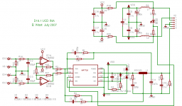
Here's a schematic of an MP7720 based amp using post filter feedback as I'd like to implement it (the values are not necessarily finalized). The title is UCD INA because it's a UCD style instrumentation amp like the Hypex modules.
The board layout for this is also finished (I spent a lot of time agonizing about all the details) but I would like to do some more experimenting with this configuration before having any boards made. Currently, the outer board dimensions are 1.875 in x 1.75 in with 0.25 in diameter mounting holes in each corner; basically the same as the boards for the previous pre-filter feedback configuration. Component spacing is tight and most of the passive components are 0805 sized surface mount parts. More to come on that stuff at a later date 😉
The board layout for this is also finished (I spent a lot of time agonizing about all the details) but I would like to do some more experimenting with this configuration before having any boards made. Currently, the outer board dimensions are 1.875 in x 1.75 in with 0.25 in diameter mounting holes in each corner; basically the same as the boards for the previous pre-filter feedback configuration. Component spacing is tight and most of the passive components are 0805 sized surface mount parts. More to come on that stuff at a later date 😉
Attachments
BWRX said:Here's a schematic of an MP7720 based amp using post filter feedback as I'd like to implement it (the values are not necessarily finalized). The title is UCD INA because it's a UCD style instrumentation amp like the Hypex modules.
The board layout for this is also finished (I spent a lot of time agonizing about all the details) but I would like to do some more experimenting with this configuration before having any boards made. Currently, the outer board dimensions are 1.875 in x 1.75 in with 0.25 in diameter mounting holes in each corner; basically the same as the boards for the previous pre-filter feedback configuration. Component spacing is tight and most of the passive components are 0805 sized surface mount parts. More to come on that stuff at a later date 😉
Hi BWRX,
Split R2 and the other resistor R? below it, (I can't read the ref des.)
Split those two into four resistors and add a cap between them.
Hope that makes sense. Think of an "H" where the vertical segments are your resistors and the horizontal segment is your R2 and R?.
Make sense?
If your layout is done, then its done, and it can be hacked in, but this is very useful in maximizing the loop feedback in my experience. If you've studied and understand Bruno's UCD AES paper, then you will see the merit of this.
It allows you to make a UCD that isn't high gain, but has lots of loop gain. In your design, with potential LM4562's at the front end, you may benifit from running the amplifier gain at say about 2, or maybe even less.
I'd be interested in one of these babies when your done.
Keep up the good work!
Be interesting how it compares to your gain clone!
Best Regards,
Mike
Hi Mike.
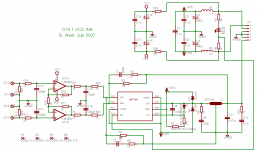
Thanks for tip! You mentioned this a page or so back but just to be sure I made the correct addition check out the attached schematic. If that is correct, there is just enough room for 4 more 0805 size parts in that area of the board, so it shouldn't be too difficult to add them.
Thanks for tip! You mentioned this a page or so back but just to be sure I made the correct addition check out the attached schematic. If that is correct, there is just enough room for 4 more 0805 size parts in that area of the board, so it shouldn't be too difficult to add them.
Attachments
BWRX said:Hi Mike.
Thanks for tip! You mentioned this a page or so back but just to be sure I made the correct addition check out the attached schematic. If that is correct, there is just enough room for 4 more 0805 size parts in that area of the board, so it shouldn't be too difficult to add them.
Brian,
Very close. Delete C19 and the AGND connection.
Make C18 connect to the resistors where C19 use to.
Make C18 a 0805 if its not already to accomidate Panasonic ECU series.
Also, you might want to add a 1210 pad for the output filter cap C11 if it isn't already. The panasonic ECP series might do well there, and it would be worth a try.
Note on these SMT film caps. Two soldering irons at 650C maxs applying heat only to the pad.
They take some practice or they puddle.
You might also add a Cap pad from the output filter cap to a solder pad for bridge applications;>). Its useful to sync them.
Something like 22nF. Make it big though, 1206, because it sees more volts. A AGND pad might also be nice so you can connect bridge amps via twisted pair. Just a wish, clearly hackable if no space.
Regards,
Mike
- Status
- Not open for further replies.
- Home
- Amplifiers
- Class D
- My 10W Mono Single-Ended modules - D10.1