Very nice, I was hoping you would try this. I'm sure you could reduce the noise some by designing a board specificaly for this configuarion(hint). 😉
Maybe if your brave, you could see how they fair with a 4ohm load also.
Maybe if your brave, you could see how they fair with a 4ohm load also.
A board specifically for bridged operation would be best to keep the connection length and noise down, but it would kind of defeat the flexibility you have with monoblocks. Of course a board with two modules that is configurable for dual mono or bridged could be done pretty easily too.
Bridged modules probably wouldn't like a 4ohm load too much because their minimum load single ended is 4 ohms. They could drive 4 ohms at lower levels but won't have enough current for the full voltage swing.
Bridged modules probably wouldn't like a 4ohm load too much because their minimum load single ended is 4 ohms. They could drive 4 ohms at lower levels but won't have enough current for the full voltage swing.
Maybe this will stir up a bit more interest 🙂
I recieved my kits today and assembled them in about 40 mins.
Sorry for the crappy pictures... only tine for a few quick snaps. Will get better ones soon 🙂
Board layout looks good, and the PCB's are of excelent quality. Will comment on sound fairly soon.
I recieved my kits today and assembled them in about 40 mins.
Sorry for the crappy pictures... only tine for a few quick snaps. Will get better ones soon 🙂
An externally hosted image should be here but it was not working when we last tested it.
An externally hosted image should be here but it was not working when we last tested it.
Board layout looks good, and the PCB's are of excelent quality. Will comment on sound fairly soon.
Well done Mike. It looks like it was professionally assembled! Did that 40 minutes include winding the toroids? If so I refuse to believe that you are human 😉
I can wind toroids pretty quickly now with my AMP3 practice 😀
The parts were well labeled and the BOM was nice, having the part location listed.
The parts were well labeled and the BOM was nice, having the part location listed.
I'm extremely jealous.
I just ordered two AMP3 kits today, wish I could have ordered a couple of those cute little fellas instead.
I just ordered two AMP3 kits today, wish I could have ordered a couple of those cute little fellas instead.
Anonymous, the AMP3 is still one of the best amps for the money right now.
I'm working on altering the enable circuit, enlarging the mounting holes/pads, moving to a surface mount inductor, and changing the layout a little. I only need a pair of amps for testing but it's more economical for me to have a minimum of 10 boards made. Thus, there will be some more kits available soon that have these changes.
I'm working on altering the enable circuit, enlarging the mounting holes/pads, moving to a surface mount inductor, and changing the layout a little. I only need a pair of amps for testing but it's more economical for me to have a minimum of 10 boards made. Thus, there will be some more kits available soon that have these changes.
BWRX said:Anonymous, the AMP3 is still one of the best amps for the money right now.
I'm working on altering the enable circuit, enlarging the mounting holes/pads, moving to a surface mount inductor, and changing the layout a little. I only need a pair of amps for testing but it's more economical for me to have a minimum of 10 boards made. Thus, there will be some more kits available soon that have these changes.
I dont think the mounting holes need to be enlarged.. The fit my M3 screws and standoffs perfectly.. 🙂 The mounting holed by the capacitors could maybe be moved a tiny bit away from the zener diodes. If the heads on the machine screws were much larger than the ones I've used, they would be contacting the pads.
I didn't run into any problems with assembly due to layout, it goes together nicely.
About going to a surface mount inductor.. Would you still be sticking with a toroid? I've got some 10mH SMT toroids here.. The problem with them is they lay down, taking up more space on the PCB. I Do they make any that stand vertically? I haven't seen any but that doesn't mean they don't exist.
🙂
The mounting holes will be enlarged a little bit but the pad diameter will be a good bit larger to accomodate screws with larger heads.
The inductors I've been looking at are shielded ferrites. So far they sound just as good as the toroids but I haven't been able to check out any waveforms with my scope to see how they compare when driven hard and in terms of EMI. The ones I've tested are 13mmx13mmx8mm and that is why I have to change the layout a bit.
They do make surface mount toroids in both lay down and stand up packages, but the lay down toroids take up a lot of space and the stand up surface mount toroids are pretty expensive.
I've just tried powering up my modules.. but no luck. LED's dont come on. The voltage at the enable pin is -10.5v.. Both modules are behaving the same. Any ideas what to check? Is there a jumper for starting the amplifier that I've missed?
No jumper. When you power up the rails the amp should just turn on.
Everything looks right from your pictures. Do you have the LEDs in the correct way?
More importantly, is power hooked up to the correct wires? Are the modules drawing any current from your supply?
V- should be -12V, V+ should be to +12V.
With 12V rails you should see about -7.8V on pin 4 (the enable pin).
Each LED is showing that each rail is powered up. If one LED goes out it means one rail went down or there is a short on that rail. If both go out then both rails went down or there is something more serious wrong!
Here's a little update on this project.
I've redesigned the boards for two different kinds of surface mount inductors. I've tested the them with the one sample and it works just as well as the toroidal inductors. I've got some samples of another type on the way and will try them out soon. I'm going to have maybe 30 boards made that will use the one inductor I think will work the best. I'm will build 4 modules for testing and about 4-6 other boards are spoken for, so that leaves about 10-11 pairs of modules left if anyone would like to buy and build up a pair. I'm asking $55 shipped in the US ($60 shipped outside the US) for a kit which includes all the necessary parts to build up two modules. You would need to find, build, or buy a +/-12V supply to power these little guys. I should have all the parts and boards in a few weeks. It will then take me a couple to a few days to transform the parts into kits.
If you're interested please get in touch with me via email.

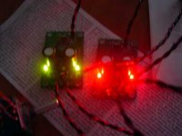
How's this? I ran out of blue so I had to use red and green on my test modules. The green ones need more current to be at a similar level of brightness. I still prefer the red or blue LEDs, even though the blue ones are a lot more expensive. Blue is a more soothing color and is generally associated with cool things (temperature wise). Since the chip runs so cool it only seems appropriate 🙂
Attachments


- Status
- Not open for further replies.
- Home
- Amplifiers
- Class D
- My 10W Mono Single-Ended modules - D10.1