'scope Q&A ....
" ... My scope is an old 15MHz Tektronix T922 so it certainly isn't top of the line ..."
I have a couple of Navy surplus Tektronics my self, and getting a decent display from those old tube type 'scopes can be a bear for the camera.
But I thought I recognized some noise in the trace pictures. ... Posts # 171 (sq. wave), # 172 (10 Hz sine wave) & # 173 (20K sine wave) in particular would make me suspect that a whole lot of noise, besides just the PS, is getting through to the amp.
" ... I almost burned my finger touching the chip doing the low frequency tests into 4ohms ..." This also indicates that the amp chip is passing more than just low freq audio information plus power supply ripple ... indicating that the power supply ripple is only a part of the problem noise.
I would suggest some form of additional filtering on the power supply rails like two inductors and matching caps on both +Vcc and -Vdd (ground).
+---|---/\/\/\---|---
....==............==
-----|---/\/\/\---|---
I'll draw a better diagram if needed, buy I would have to review the PS circuit.
upon further research ...
.... after I reread the earlier parts of this thread, I now believe that what I said above is true ... in order to get that PS noise and other noise off of this system, there should be some "hum-bucking" coil inductors in both rails AND the ground path ...
+---|---/\/\/\---|--- +
....==............==
-----|---/\/\/\---|--- gnd
......| ............==
- ---|---/\/\/\---|--- -
(3) inductors about 20 uH (~25 turn air coil, #16 AWG, ~0.6" diameter).
(1) Poly Cap across +/- rails about .22 uF, quality audio type, 100V rated.
(2) Caps between + / gnd / - rails about 2900 pF (2.7 to 2.9 nF), ceramic or any type, 100V rated.
This would be good filtration of all frequencies above 75K Htz. to 100K Htz. (everything above audio range). This can be applied to any switching supply or "standard" torrid transformer type supply for rail voltages from +/- 9 VDC to +/- 50 VDC.
I'll build a couple of these and forward some pics.
...
Re: 'scope Q&A ....
Any ripple on the supply lines is not from the supply but from the amp's output stage. Class d requires careful attention to layout of the power traces, filtering, and decoupling. There is already adequate filtering on the PCB in the form of a CLC network, and it's not the first time I've used it in my designs either 😉
Yes, it's not terribly easy for the camera, but it's definitely doable.FastEddy said:I have a couple of Navy surplus Tektronics my self, and getting a decent display from those old tube type 'scopes can be a bear for the camera.
In the low frequency photos the camera's shutter speed is very slow so it can capture the scope tracing the entire waveform. That "noise" isn't actually noise. It is the switching residual that gets through the output filter. You will see that with any PWM class d amp.FastEddy said:But I thought I recognized some noise in the trace pictures. ... Posts # 171 (sq. wave), # 172 (10 Hz sine wave) & # 173 (20K sine wave) in particular would make me suspect that a whole lot of noise, besides just the PS, is getting through to the amp.
The power supply is more than adequate, there is plenty of filtering, and the PCB layout (especially with respect to decoupling the supply rails) is pretty good.FastEddy said:This also indicates that the amp chip is passing more than just low freq audio information plus power supply ripple ... indicating that the power supply ripple is only a part of the problem noise.
I would suggest some form of additional filtering on the power supply rails like two inductors and matching caps on both +Vcc and -Vdd (ground).
Any ripple on the supply lines is not from the supply but from the amp's output stage. Class d requires careful attention to layout of the power traces, filtering, and decoupling. There is already adequate filtering on the PCB in the form of a CLC network, and it's not the first time I've used it in my designs either 😉
Re: 'scope Q&A ....
That just means that the 180mohm output fets on the chip are dissipating a lot of heat at maximum output. This is definitely to be expected especially since they are in a rather small SO8 package - not very efficient heat transfer to the air.
I would have used wirewound inductors instead of ferrite chip inductors for power supply filtering but that would really make these modules a lot larger. My main design criteria was to make the PCB as compact as possible without compromising the layout.
FastEddy said:" ... I almost burned my finger touching the chip doing the low frequency tests into 4ohms ..." This also indicates that the amp chip is passing more than just low freq audio information plus power supply ripple ... indicating that the power supply ripple is only a part of the problem noise.
That just means that the 180mohm output fets on the chip are dissipating a lot of heat at maximum output. This is definitely to be expected especially since they are in a rather small SO8 package - not very efficient heat transfer to the air.
I would have used wirewound inductors instead of ferrite chip inductors for power supply filtering but that would really make these modules a lot larger. My main design criteria was to make the PCB as compact as possible without compromising the layout.
Okey ...
" ... That "noise" isn't actually noise. It is the switching residual that gets through the output filter. You will see that with any PWM class d amp. ..."
Yes, but don't you want that switching residual removed from the amp output?? One would think that removing all the EMF / transients / etc from the PS would help.
" ... This is definitely to be expected especially since they are in a rather small SO8 package - not very efficient heat transfer to the air. ..."
I go by the old rule: If it burns the flesh, its too hot ... and anything other than the audio signal that consistantly gets through the output stage of any amp is a waste of power ... the power being radiated as heat.
I go by the old rule: If it burns the flesh, its too hot ... and anything other than the audio signal that consistantly gets through the output stage of any amp is a waste of power ... the power being radiated as heat.
also ...
... I went home for lunch and put together this filter anyway as I intend to use it in an other area ... it took about 30 minutes.
+---|---/\/\/\---|--- +
....==............==
-----|---/\/\/\---|--- -
... I went home for lunch and put together this filter anyway as I intend to use it in an other area ... it took about 30 minutes.
+---|---/\/\/\---|--- +
....==............==
-----|---/\/\/\---|--- -
Re: also ...
180mohm FETs conducting about 2Arms will dissipate about 0.7W a piece. That's 1.4W for both output FETs that has to be dissipated by the SO8 package at max power (15W) into 4 ohms. That's a lot of heat, and is more than enough to make the case hot enough to burn your finger. Assuming not much other dissipation is going on that's about 90% efficient, which is really quite good. Even more amazing is that the chip didn't go into thermal protection!
That's the exact filter scheme used on these modules. Although the ferrite chip inductors I use are intended to reduce the higher frequency garbage from getting into or out of the amp through the supply rails. Grounding is a whole nother story, but inductors should not be used between power and signal grounds.
Yes you do want it removed. The problem is that lowering the cutoff frequency of the output filter lowers the frequency at which peaking occurs, can bring the phase shift down into the audbile range, and requires physically larger components. It's a trade off and a filter with a higher cutoff will have more residual at the output and a little more noise.FastEddy said:Yes, but don't you want that switching residual removed from the amp output?? One would think that removing all the EMF / transients / etc from the PS would help.
I go by that rule too, but there's only so much you can do to heatsink an SO8 package... The higher amplitude of the switching residual is being wasted as heat in the output impedance, not in the output FETs. It's the output filter that determines how much it gets attenuated.FastEddy said:I go by the old rule: If it burns the flesh, its too hot ... and anything other than the audio signal that consistantly gets through the output stage of any amp is a waste of power ... the power being radiated as heat.
180mohm FETs conducting about 2Arms will dissipate about 0.7W a piece. That's 1.4W for both output FETs that has to be dissipated by the SO8 package at max power (15W) into 4 ohms. That's a lot of heat, and is more than enough to make the case hot enough to burn your finger. Assuming not much other dissipation is going on that's about 90% efficient, which is really quite good. Even more amazing is that the chip didn't go into thermal protection!
FastEddy said:... I went home for lunch and put together this filter anyway as I intend to use it in an other area ... it took about 30 minutes.
+---|---/\/\/\---|--- +
....==............==
-----|---/\/\/\---|--- -
That's the exact filter scheme used on these modules. Although the ferrite chip inductors I use are intended to reduce the higher frequency garbage from getting into or out of the amp through the supply rails. Grounding is a whole nother story, but inductors should not be used between power and signal grounds.
That's funny, its the same one ...
" ... That's the exact filter scheme used on these modules. Although the ferrite chip inductors I use are intended to reduce the higher frequency garbage from getting into or out of the amp through the supply rails. Grounding is a whole other story, but inductors should not be used between power and signal grounds. ..."
Yes it is ... just double coils instead of single coils ... and it is the exact same as many "line filters" used to fliter anything above ~ 500K Htz. ... same as EMI filters on line cords, etc.
The whole exercise I was trying to point out is ... the nature of two inductors instead of one in any kind of filter circuit, power supply, line side, load side or output ... when properly tuned for the desired frequencies, they do both, filter outgoing signal of unwanted transients AND filter the same incoming return power output = In this case a coil & cap combination on the power output and another on the return line = a "tank" circuit resonating above the audio and eliminating the PS transients, switching residuals, etc. by cancelation ... (There are mechanical and hydraulic equivelents).
" ... lowering the cutoff frequency of the output filter lowers the frequency at which peaking occurs, can bring the phase shift down into the audbile range ..." ... but you don't have to lower anything, just set the tank resonance frequency to the right level below your switching frequency and the double inductor circuit "cancels" all above it.
" ... Grounding is a whole nother story, but inductors should not be used between power and signal grounds. ..."
Yes, a coil connected between + XX Volts and Ground is a dead short @ DC ..... Zzzzztttt.
Perhaps my crude drawing is missleading ...
+ ---|---/\/\/\/\----|----- + plus side power rail
......cap..............cap
- ----|---/\/\/\/\----|----- - gnd (or minus side rail)
Re: That's funny, its the same one ...
If you're suggesting LCLC, it would certainly be doable. I just chose the use only a CLC for reduced cost and space.
If you're suggesting CLC with an inductor between the caps ground connection, that could be done too but I'd have to add two inductors since I have separate ground returns for each half of the supply.
I had considered providing more filtering options but went with the CLC as a design compromise.
I'm a little confused, are you saying to use an LCLC filter between each rail and ground, or CLC filter with capacitors between each rail and ground and inductors between the caps on the + rail, the - rail, and the ground connections?FastEddy said:The whole exercise I was trying to point out is ... the nature of two inductors instead of one in any kind of filter circuit, power supply, line side, load side or output ... when properly tuned for the desired frequencies, they do both, filter outgoing signal of unwanted transients AND filter the same incoming return power output = In this case a coil & cap combination on the power output and another on the return line = a "tank" circuit resonating above the audio and eliminating the PS transients, switching residuals, etc. by cancelation ... (There are mechanical and hydraulic equivelents).
If you're suggesting LCLC, it would certainly be doable. I just chose the use only a CLC for reduced cost and space.
If you're suggesting CLC with an inductor between the caps ground connection, that could be done too but I'd have to add two inductors since I have separate ground returns for each half of the supply.
I had considered providing more filtering options but went with the CLC as a design compromise.
This is obviously implemented in bridged output stages, and you can take it a step further by using coupled inductors (I tried this with the Tripath amps and it worked just fine), but I didn't want to complicate grounding layout by adding another inductor in the return line. I also didn't want to compromise the output ground reference, which the current configuration is sensitive to.FastEddy said:" ... lowering the cutoff frequency of the output filter lowers the frequency at which peaking occurs, can bring the phase shift down into the audbile range ..." ... but you don't have to lower anything, just set the tank resonance frequency to the right level below your switching frequency and the double inductor circuit "cancels" all above it.
I meant an inductor between the power ground and the signal ground. I would hope that everyone knows an inductor across a DC voltage is bad thing 🙂FastEddy said:Yes, a coil connected between + XX Volts and Ground is a dead short @ DC ..... Zzzzztttt.
suggesting ...
" ... I'm a little confused, are you saying to use an LCLC filter between each rail and ground, or CLC filter with capacitors between each rail and ground and inductors between the caps on the + rail, the - rail, and the ground connections? ..."
Yes
" ... I'm a little confused, are you saying to use an LCLC filter between each rail and ground, or CLC filter with capacitors between each rail and ground and inductors between the caps on the + rail, the - rail, and the ground connections? ..."
Yes
suggesting
" ... I'm a little confused, are you saying to use an LCLC filter between each rail and ground, or CLC filter with capacitors between each rail and ground and inductors between the caps on the + rail, the - rail, and the ground connections? ..."
Yes, I'm suggesting any or all of the above.
CLC for the PS rails = one each (effectively sharing the caps):
+ ---|---/\/\/\/\----|----- + plus side power rail
......cap..............cap
- ----|---/\/\/\/\----|----- - gnd (or minus side rail)
......... OR .......
CLC on PS + rail, LC on PS ground rail & CLC on PS - rail:
+---|---/\/\/\---|--- +
....==............==
-----|---/\/\/\---|--- gnd
......| ............==
- ---|---/\/\/\---|--- -
......... AND / OR ..........
And / or a modification to the output of the amp so that there are two inductors, one each on + output, and - output = an LCLC (or similar) tuned to the existing output filter freq. (The idea here is a "tank trap" set to the switching PS / switching amp residual frequency.
...
(Sorry to seem so criptic, but I have not carefully examined the output stage of the amp.)
BWRX said:To everyone who has a kit on the way - I just sent each of you emails containing documentation that will help with assembly.
I haven't received this, can anyone e-mail me a copy?
Ta,
Keith
Hi Keith - didn't you get the email I sent? I'll send it from my other email address to both of yours and see if it gets through. I think that my mail may have been caught by your spam filter like last time... Hopefully this one will get through.
Hi Brian,
got the doc - it turned out that as I had to use my business e-mail account while roughing it @ Yellowstone, the company changed I-mail software, and I didn't see any incoming.
So now I've got the kit, a set of new bits for my iron, ultrasonic cleaner, flux pen, bench dual psu, surgical masks, and various (contradictory) monograms on smd soldering - just waiting on illuminated magnifier (out of stock) and I'll be in a position to convert various small components into unrecognisable charred lumps.
Regards,
Keith.
KeithC said:So now I've got the kit, a set of new bits for my iron, ultrasonic cleaner, flux pen, bench dual psu, surgical masks, and various (contradictory) monograms on smd soldering - just waiting on illuminated magnifier (out of stock) and I'll be in a position to convert various small components into unrecognisable charred lumps.

Godspeed sir.
Don't be shy to ask questions that may come up on your perilous journey 😉
I haven't heard from anyone regarding the status of their build so I thought I'd ask: how's everyone coming along with these? If anyone has any questions at all, or is having problems, please get in touch with me. I'll do my best to help you get the modules up and running. I know one person was having trouble and contacted me but he has not replied to any of my emails after our first few exchanges. Hopefully they weren't caught in a spam filter...
Also, attached is a schematic of how you can get regulated +/- supplies with two three terminal positive voltage regulators. It's simple and works quite well. I've been using a setup like this from the beginning. Please note that you need to use a transformer with electrically isolated secondaries for this to work. You can not use this schematic on a transformer with a center tapped secondary.
Also, attached is a schematic of how you can get regulated +/- supplies with two three terminal positive voltage regulators. It's simple and works quite well. I've been using a setup like this from the beginning. Please note that you need to use a transformer with electrically isolated secondaries for this to work. You can not use this schematic on a transformer with a center tapped secondary.
Attachments
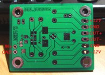
Brian, for my part, I'm awaiting some power supplies. I did want to thank you for putting the kits together, and particularly for designing the circuit boards. I'm still somewhat shocked how small they are ... my goodness things have changed.
Once I receive the power supplies, I'll compare them to some tube amps I'm building. The latter are 6C45 spuds using regulated Vicor SMPSs + CLC power supply regulation. This amp will be even simpler than the D10s with one tube, one transformer and two resistors. If these amps cannot better these little class D chips, I can't see how any tube amp could. Will be an interesting comparison.
Once I receive the power supplies, I'll compare them to some tube amps I'm building. The latter are 6C45 spuds using regulated Vicor SMPSs + CLC power supply regulation. This amp will be even simpler than the D10s with one tube, one transformer and two resistors. If these amps cannot better these little class D chips, I can't see how any tube amp could. Will be an interesting comparison.
Him Tom. You are most welcome. So you're waiting on the power supplies, eh? I'll bet that's what is hanging everyone else up too. I can't wait to hear about your amp comparo. Sounds like quite a line up you've got planned. Those tubes are probably about the size of one module aren't they? 😉
- Status
- Not open for further replies.
- Home
- Amplifiers
- Class D
- My 10W Mono Single-Ended modules - D10.1