TOINO said:I have only one layout question:
From where do you sense the feedback signal on your big output cooper area?
From a little track extension at the end, between the last emitter resistor and the output point. Basically, the point at which the only track current flow is to and from the load.
Cheers,
Glen
PS
Your amp looks really nice, but I reckon your power rails and output copper area are much longer than mine

G.Kleinschmidt said:
PS
Your amp looks really nice, but I reckon your power rails and output copper area are much longer than mine
You are right about copper length; that fact alone justifies unusual layout.
http://www.diyaudio.com/forums/showthread.php?postid=1212098#post1212098
This topology simplifies things a lot… output could be the dissipator… and no transistor insulators…
In that case big output node antenna/capacitance is gratis… 😱 …be care
 ..sensitive circuits..
Additionally it is very easy to force and sustain high output impedance for soft-start-up or protection proposes.
Also I have not output coil mostly because of this http://www.diyaudio.com/forums/showthread.php?postid=1213653#post1213653
Instead of that, I guarantee you that the amplifier is rock stable mainly because of the layout.
Anyway, your propose is different. Your amplifier is class-A (more precisely, Frankenstein class-A
) and mine has to many compromises to be classified on your race. 
Attachments
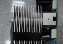
Besides you have “real thermal mass” to handle power peaks…
And they are very easy to build, if you could live with the required fan (noise).
Indeed, very efficient and compact at ground (pcb) level…
And they are very easy to build, if you could live with the required fan (noise).
Indeed, very efficient and compact at ground (pcb) level…
Glen are you still building and testing this thing, im still interested to hear about the results?
Craig405 said:Glen are you still building and testing this thing, im still interested to hear about the results?
Still building, working well so far, but not nearly fully operational yet.
Cheers,
Glen
Hi Glen,
Your "home.htm" is missing.
http://users.picknowl.com.au/~glenk/HOME.HTM
Your "home.htm" is missing.
G'day.
The whole site is now down (and will be for probably quite a while), being revamped and updated.
Cheers,
Glen
The whole site is now down (and will be for probably quite a while), being revamped and updated.
Cheers,
Glen
jacco vermeulen said:Oink.
Moo.
Sorry, my sentiment expressed in post 174 has not changed. The design has been proven and works very well, but the heatsinks have been requisitioned and sliced for another amplifier (K800AB), which now has priority. The A+ amplifier will be eventually put togeather as a pair of mono blocks.
I have lost any incentive to detail/share the design further here.
In hope to have all the details of the completed/working K800AB amplifier up on my website by Christmas. This is all taking me much longer than I had hoped due to too many other commitments. Currently laying out the final iteration of last PCB – H/V amplifier / triggered sweep generator for the built-in DG7-32 based signal monitoring cathode ray oscilloscope.
Over,
Glen
Yeah, i gathered you spend way too much time in the stinky desert.
No sense to feed the herd anyway if it isn't simple and cheap.
The image of SJ with a guitar and singing Kumbaya just made me wonder if you planned to finish the Kleinics A+
Leaving it alltogether is a bit of a shame for such an innovative concept.
Out.
No sense to feed the herd anyway if it isn't simple and cheap.
The image of SJ with a guitar and singing Kumbaya just made me wonder if you planned to finish the Kleinics A+
Leaving it alltogether is a bit of a shame for such an innovative concept.
Out.
Hello,
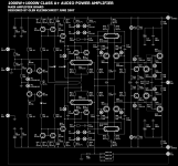
Could you maybe please repost the schematic here so people who missed the thread (like me) can see it? It would be very nice of you!
Regards
Could you maybe please repost the schematic here so people who missed the thread (like me) can see it? It would be very nice of you!
Regards
lineup said:
in order to give an output 1000 Watt RMS Class A
we need more than 500 Watt idle power, per channel
Hi Lineup,
But isn't the amp in this thread a class A+ amp, only the low voltage amp runs class A.
Link
lineup said:unless glen has a later version
here is a copy i have
🙂
note:
in order to give an output 1000 Watt RMS Class A
we need more than 500 Watt idle power, per channel
Thanks Lineup.
BTW, there is a boo boo in that schematic. D13 and D14 need to be higher voltage types.
Cheers,
Glen
Glen,
I've been reading this thread but too many missing links cited. Would you mind posting them somewhere convenient?
Cheers
Atiq
I've been reading this thread but too many missing links cited. Would you mind posting them somewhere convenient?
Cheers
Atiq
atiq19 said:posting them somewhere convenient?
Yes, on my www
I'm working through the projects on the list there. Don't hold your breath though. I'm not predicting any timelines anymore because unforseen **** keeps getting in the way. I don't know where the last 12 months went..........................................
- Status
- Not open for further replies.
- Home
- Amplifiers
- Solid State
- My 1024W RMS CLASS A+ amplifier.