Just the series current limiting resistor...
A resistor of at least 100R is compulsory at the output of any opamp driving a cable. It does not need to be added just for current limiting.
This time you're right, as a low-ohmish resistor in the output line disburdens the opamp's task of driving a capacitive load like an interconnect cable.
Best regards!
Best regards!
A resistor of at least 100R is compulsory at the output of any opamp driving a cable. It does not need to be added just for current limiting.
Depends on the opamp - check the datasheet (its not always quoted though). 100 ohms works with many, but some can drive down as low as 0.2 ohms into highly capacitive loads (THS4281) - useful for generating precision low-impedance voltage references, 0.2 ohms straight into filtercap into an ADC reference pin, very low impedance reference from DC to daylight.
Almost all opamps have internal indefinite current limiting. Can't think why, they'd sell so many more if not (!)
I made something similar in my '' basic preamp '' it work and I dont expect any problem, The circuit short to ground the output via a 100 ohms resistor, most of the time the preamplifier is set to give at the output a voltage below 1 volt to have a usefull sound level so current is limited to a few mA for only a second or so . See ''basic peamp circuit '' thread.
I have OPA134 application note and in '' absolute rating '' it is written : Output short circuit to ground..... one amplifier per package ...... continuous.
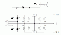
I also think that te circuit to drive the relay can be made cheaper , in circuit below select the relay an the zener diode so that pick-up voltage will be above minimum input vottage of regulators, so relay will pick up only if regulators are working..... This will not give any delay but should be tested.
I also think that te circuit to drive the relay can be made cheaper , in circuit below select the relay an the zener diode so that pick-up voltage will be above minimum input vottage of regulators, so relay will pick up only if regulators are working..... This will not give any delay but should be tested.
Attachments
Yes that's a great idea but place it after the regulators then both rails have to be definitely present for the relay to operate. Adding delay could be done with cap and diode added to the relay arm of the circuit.
No I would keep it as is and calibrate for 15 + 15 + 3 +3 = 36 volts so relay will pick up only after both regulators are working.
At shutdown OP-amp makes problem when voltage is very low and polarisation is about to give-up and you get oscillations.....
At shutdown OP-amp makes problem when voltage is very low and polarisation is about to give-up and you get oscillations.....
But that doesn't check that the regulators are actually working. Only sensing the voltage after the regulators can tell if one or both have gone into thermal shutdown or short-circuit protection, or just fallen off the board(!)
- Home
- Source & Line
- Analog Line Level
- Muting opamp outputs
