There is a technical explanation for the metallic box with a trafo inside it - the top becomes the last trafo winding...
//
Good point. But I rarely see people use floating signal grounds... isn’t the ground wire supposed to drain voltage from the chassis?
Ground and chassis seem hard - thats why avoid them 😉
Preferred interconnection is differential balanced.
//
Preferred interconnection is differential balanced.
//
Ground and chassis seem hard - thats why avoid them 😉
Preferred interconnection is differential balanced.
//
Fully agree on both counts.
Btw, is anyone aware of the clocking scheme Totaldac uses? Not much is disclosed and i cannot spot two nice big oscillators on board. Does it use a very large fifo which can cope with clock discrepancies by being large, or is it a PLL clock? It apparently does not support external clock sources, which perhaps points towards a pll.
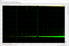
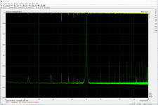
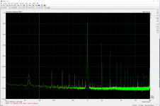
Did some more measurements with the basic soundcard and a number of questions came up. Both the buffered and raw balanced outputs seem fine. S/N is about 130db balanced buffered, crosstalk <-120db. S/N in raw output is beyond the -140db noise floor of the Behringer. If the Behringer could take 0db without clipping then the THD number should be <0.006% for raw balanced. Given higher input impedance on the measuring device distortion might drop a little too. It was baffling that the Behringer showed huge harmonics variation in the two input channels when using balanced, but no difference with SE. Screenshot 1 is balanced raw left channel with different Behringer input channels overlay, 2 and 3 are balanced buffered L/R using Behringer input 1 and 2 respectively.
The most confusing part is SE outputs. Huge harmonic distortions in both raw and buffered outputs. Also seeing much more mains noise in right channel SE buffered than the left. At the very least, the results seem to explain the poor SE headphone performance well. Screenshot 4 is SE buffered L/R overlay, 5 is SE raw left channel with different Behringer input channels overlay (note the close match compared to balanced). I also couldn't get the SE to output anything close to 0db which is very strange since balanced needs ~10db attenuation, much larger than the usual level difference between the two outputs.
All 4 ladders match pretty closely with each other.
Edit: the mains noise in SE buffered (as well as balanced raw, and probably balanced buffered as well) goes away completely with the UI transformer unplugged. Whether the top cover was installed didn't matter this time.
Attachments


Last edited:
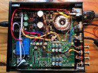
Here's what my build looks like for the record. The blue rectangular transformer is the UI-type that came with the SK Lite kit. I will be in the market for another shielded toroidal to stack on the existing one sometime in the future.
Things are a bit packed, but the buffered output connectors are in the upper-left corner.
Things are a bit packed, but the buffered output connectors are in the upper-left corner.
Attachments
Last edited:
The most confusing part is SE outputs.
You are using two boards, right? How are the SE outputs connected?
Re ref music:
Found this recording today:
G.P. Telemann: Fantasias for Viola da Gamba | Robert Smith | Resonus Classics | RES10195
TIDAL: Listen to Telemann: Fantasias for Viola da Gamba on TIDAL
Not a trace of hardness, just glorious definition and space. Wonderful music and execution.
A few of my goto ref. tracks: (_se, whats hifi without music?)
//
Attachments

Last edited:
You are using two boards, right? How are the SE outputs connected?
Raw are drawn from the board directly with short wires, paralleled with balanced output. Buffered is drawn from the negative output of the inverted channel to keep them independent from balanced output. You can see how the RCA connectors are soldered.I’m just confused why the same raw output pins measure so differently in SE and balanced.
"Also seeing much more mains noise in right channel SE buffered than the left."
One side (channel?) of your board is very close to a rectifier and in general closer to the mains trafo and even if potted and shielded, there will be some leakage.
If you have a scope - take a probe and make a short loop from the tip to the ground clip with a piece of cable and move it around inside the box studying the screen to see where you have might have EMI problems.
I would move the mains out of the box to get rid of all mains related fields. Also, no switchers only passive regulators close, i.e. inside box, to audio carrying gear.
"All 4 ladders match pretty closely with each other."
How could you tell? On one board there are 2 channels using 2 rows of resistors each. Each of these 2 channels are native SE. The balancing "act" is created by the OP-amp stage. You can configure one board to be true balanced via a uManager command.
Which mode are you operating in - I became uncertain... I have supposed 1 board - stereo.
//
Last edited:
Raw are drawn from the board directly with short wires, paralleled with balanced output. Buffered is drawn from the negative output of the inverted channel to keep them independent from balanced output. You can see how the RCA connectors are soldered.I’m just confused why the same raw output pins measure so differently in SE and balanced.
Not clear. Are you using two stacked boards? If yes, how is each board contributing to the se outputs?
TNT, thanks for the observations. The rectifier is only for mains earth, so it should be fine. In practice, the SE buffered out uses ladders on the other side. More importantly, all noise goes away when the UI trafos is disconnected. My EMI problem should be solved once I replace that trafos.
I’m stacking two boards and I measured all four channels to have almost indistinguishable distortions. The top board is left channel.
Analog_sa, the raw SE outputs are connected to the RCAs. You can see the connections in the photo. For buffered, left channel is taken from top board left/cold channel negative buffered out, right channel is taken from the corresponding pin on the bottom board. This way both channels should still have the original polarity.
Last edited:
What do you mean with "only for earth"?
//
It’s the ground loop breaker between chassis/mains earth and signal earth. There shouldn’t be much current going through it either normally.
Maybe the SE distortion is caused by the measuring equipment? It seems very difficult to find a reasonable explanation
Edit: Okay so I measured my laptop SE output and the distortion is almost as high as dam1021, though laptop output level is slightly lower and THD is slightly lower. This is good enough evidence for me that the Behringer SE input is completely unreliable, since I believe my laptop delta-sigma soundcard should have a very low THD. I guess this also means that I still haven't found a good explanation for why SE buffered sounds worse than Bal. Btw, I'm using a TRS to TS cable for the buffered SE measurement and RCA to TS cable for raw, but I don't think the cables are the problem.
Edit: Okay so I measured my laptop SE output and the distortion is almost as high as dam1021, though laptop output level is slightly lower and THD is slightly lower. This is good enough evidence for me that the Behringer SE input is completely unreliable, since I believe my laptop delta-sigma soundcard should have a very low THD. I guess this also means that I still haven't found a good explanation for why SE buffered sounds worse than Bal. Btw, I'm using a TRS to TS cable for the buffered SE measurement and RCA to TS cable for raw, but I don't think the cables are the problem.
Last edited:
Often the TRS double as XLR...
Since when is a rectifier bridge a grid breaker? Ref. to this?
//
Since when is a rectifier bridge a grid breaker? Ref. to this?
//
Often the TRS double as XLR...
Since when is a rectifier bridge a grid breaker? Ref. to this?
//
Yes. But I don't see why it shouldn't work for SE. It was completely unexpected that the Behringer performs so poorly; I may have a bad unit.
The grid breaker is a 10R + 0.1uF and the bridge rectifier is only there in case there's a huge voltage difference between signal and mains ground.
No, it has no impact probably (bridge or TRS) - I never saw that bridge design so I was curious.
//
//
No, it has no impact probably (bridge or TRS) - I never saw that bridge design so I was curious.
//
It's just a standard grid breaker, only I soldered the resistor and cap directly on the rectifier to save space. You can probably find PCBs for a more standard setup.
Might get a Emu0404 if the price is good. But it doesn't matter much at this point. Seems everything is good except for the UI trafo.
- Status
- Not open for further replies.
- Home
- Source & Line
- Digital Line Level
- Musings on soekris Reference Dac Module